Method for switching a multimedia source and multimedia sink from an operating mode to a standby mode, and from a standby mode to an operating mode
a multimedia source and sink technology, applied in the field of switching a multimedia source and a multimedia sink from an operating mode to a standby mode, and from a standby mode to an operating mode, can solve the problems that users may, therefore, not always determine the mode of operation of the source, and achieve the effect of quick determination and saving power consumption
- Summary
- Abstract
- Description
- Claims
- Application Information
AI Technical Summary
Benefits of technology
Problems solved by technology
Method used
Image
Examples
first embodiment
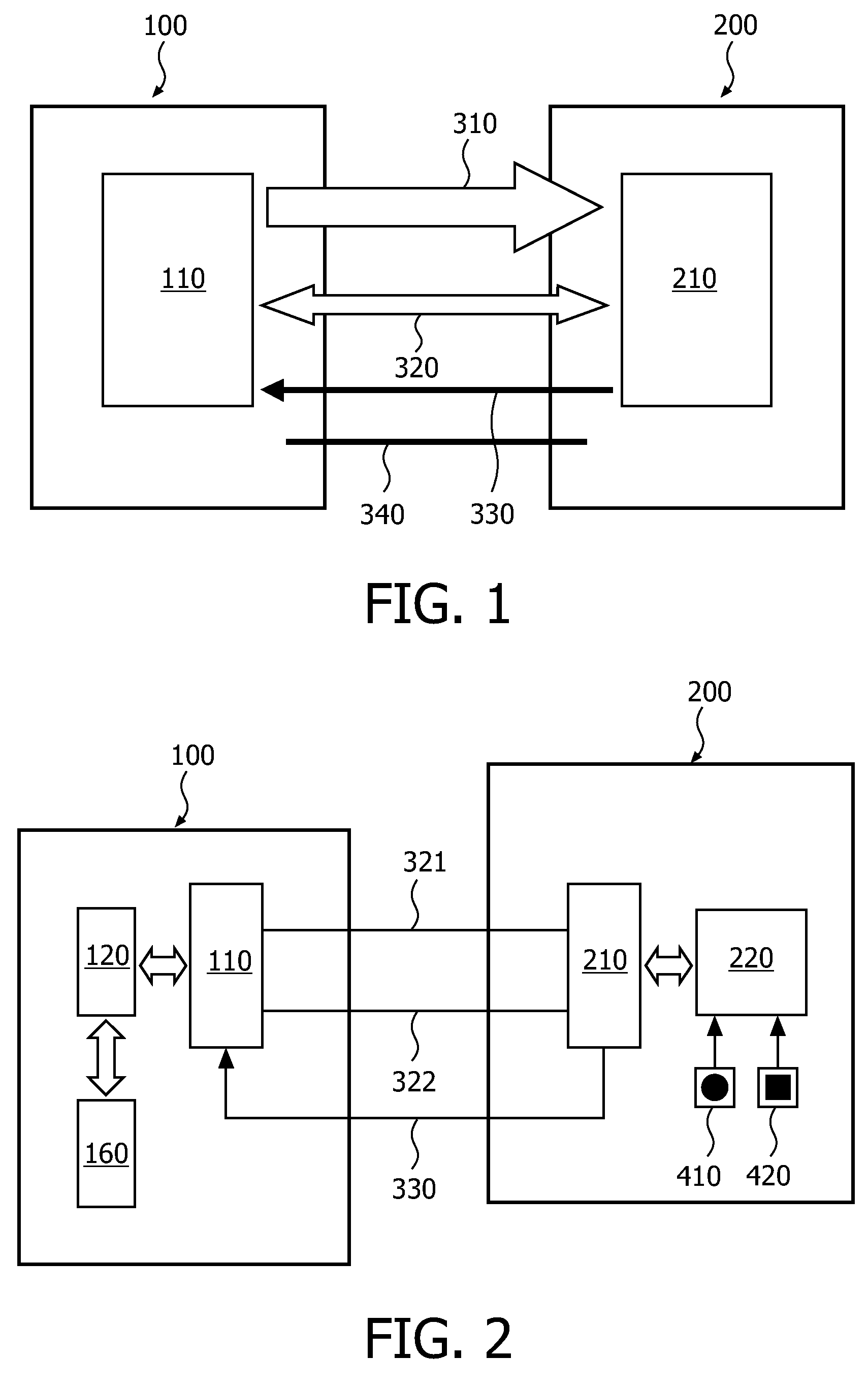
[0085]FIG. 2 depicts an example of interfacing between a multimedia source and multimedia sink using the DisplayPort standard according to the invention, which allows synchronization of the standby modes of a source and a sink. Note that the main link connections to the transmitter (110) and receiver (210) are not depicted.
[0086]A multimedia source (100) comprises a transmitter (110), a main controller (120) and a standby controller (160). The transmitter (110) is connected to a first channel, the auxiliary channel (321, 322), for link management and sink device (200) control—the auxiliary channel comprises one differential pair (321, 322) transporting self-clocked data. The transmitter (110) is also connected to a second channel, the HPD line (330), for receiving interrupt requests (IRQ) generated by the sink device. The main controller (120) is linked by data pathways to the transmitter (110) for receiving IRQ requests, and also for supplying the transmitter (110) for the informat...
second embodiment
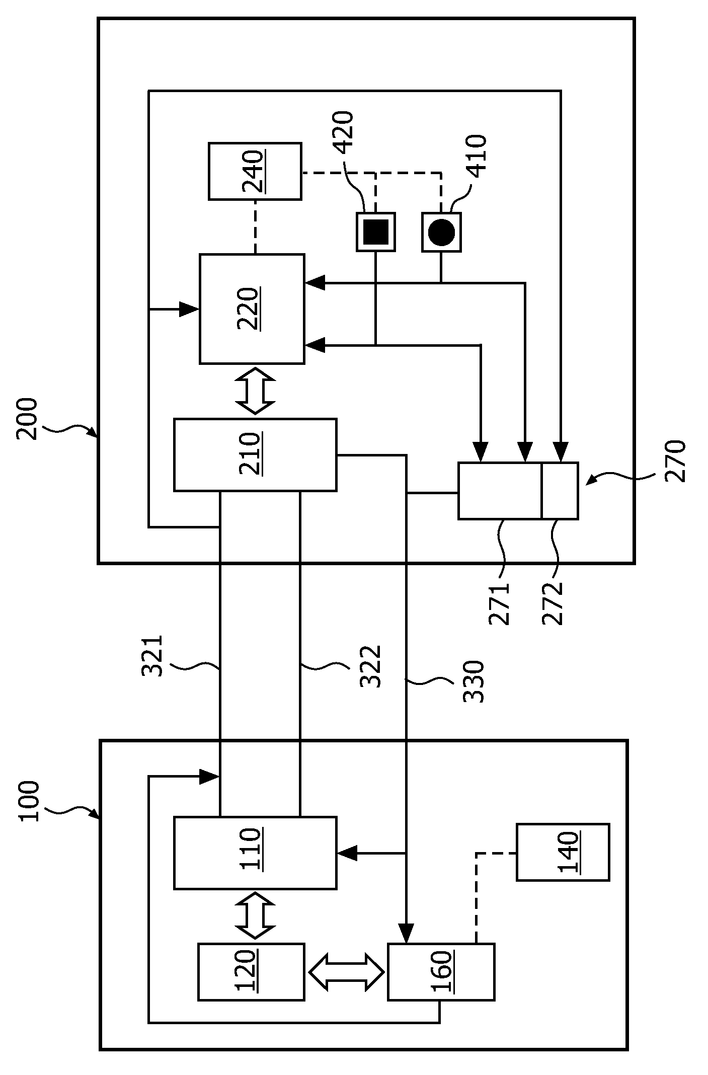
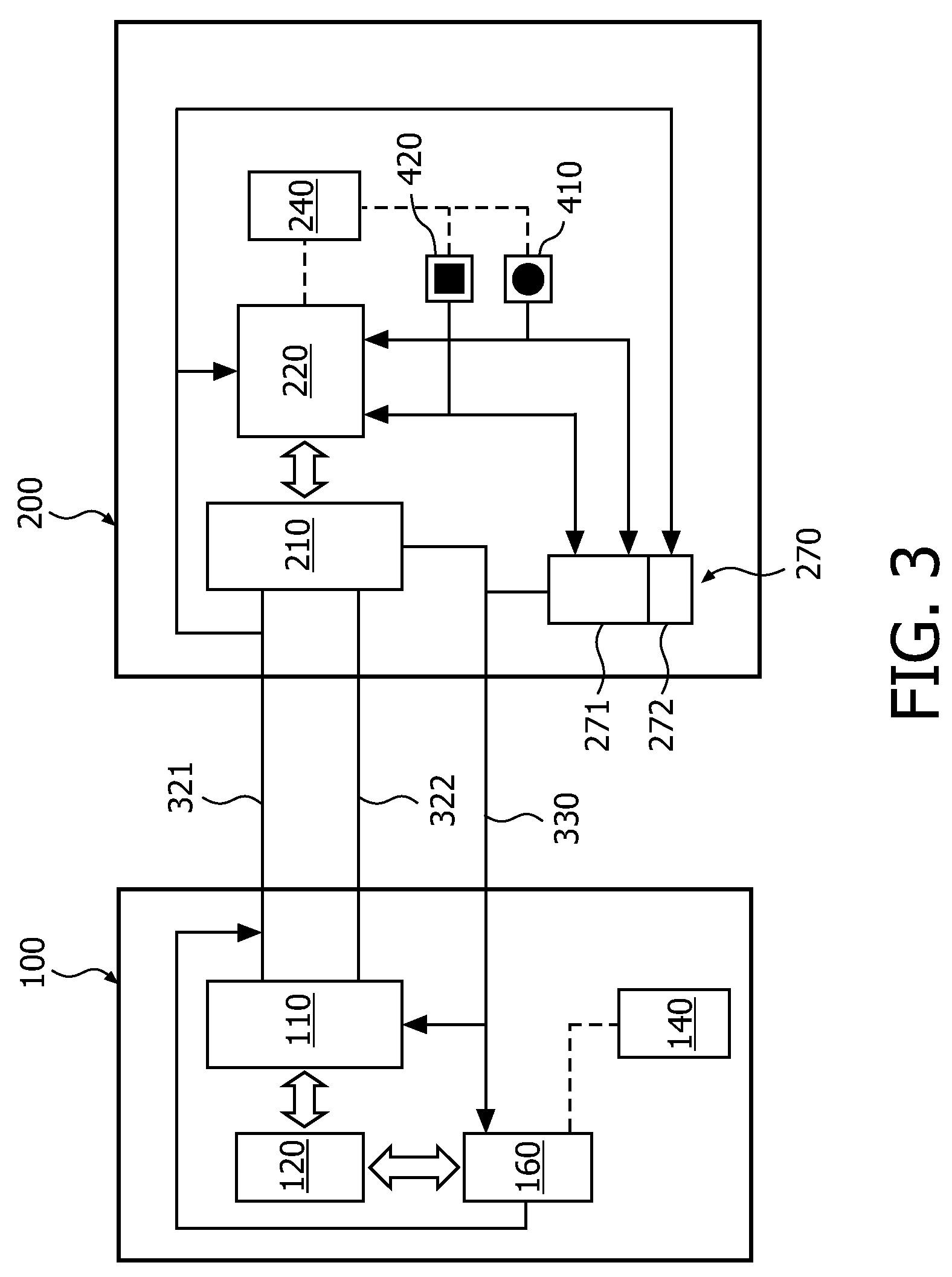
[0099]FIG. 3 depicts a multimedia source (100) and a multimedia sink (200), configured to operate according to the DisplayPort standard and the methods of the invention. FIG. 4 depicts more details of the multimedia source depicted in FIG. 3, and FIG. 5 depicts more details of the multimedia sink depicted in FIG. 3. The embodiment of FIG. 3 is the same as the embodiment of FIG. 2, except for the differences described below.
[0100]The standby controller (160) is connected to the HPD line (330) to receive HPD signals and interrupts, and it is also connected to one of the lines (321) of the auxiliary channel (321, 322). It will be apparent to the skilled person that the standby controller (160) may be connected to either of the differential pair (321, 322). The connection to the auxiliary line (321) is configured such that the standby controller (160) may vary the dc-level of the auxiliary line (321). This cannot be performed by the transmitter (110) because according to the DisplayPort...
third embodiment
[0123]Alternatively, the invention may be adapted such that the source (100) does not comprise a standby power supply (140). The source (100) and sink (200) are then further configured to connect the sink standby power supply (240) to the standby controller (160) in standby mode via the power line (340).
[0124]The general advantage to a common standby power supply is that the power consumption during standby mode becomes more predictable. This predictability is often important when configuring a system or devices to comply with power consumption requirements and regulations.
[0125]To maintain compatibility with the DisplayPort standard may be maintained by configuring the second channel (330) is to convey a low logical state in standby mode when no wake-up request is generated by the multimedia sink (200), and by configuring the multimedia sink (200) to generate the wake-up request in standby mode by asserting a high logical state via the second channel (330).
[0126]It may be advantage...
PUM
 Abstract
Description
Claims
Application Information
 - R&D
- Intellectual Property
- Life Sciences
- Materials
- Tech Scout
- Unparalleled Data Quality
- Higher Quality Content
- 60% Fewer Hallucinations
Browse by: Latest US Patents, China's latest patents, Technical Efficacy Thesaurus, Application Domain, Technology Topic, Popular Technical Reports.
© 2025 PatSnap. All rights reserved.Legal|Privacy policy|Modern Slavery Act Transparency Statement|Sitemap|About US| Contact US: help@patsnap.com


