Pattern structures in semiconductor devices

Active Publication Date: 2011-03-17
SAMSUNG ELECTRONICS CO LTD
View PDF5 Cites 19 Cited by
  • Summary
  • Abstract
  • Description
  • Claims
  • Application Information

AI Technical Summary

Benefits of technology

[0034]According to example embodiments of the present general inventive concept, a pattern structure having a minute pattern and a pad connected with the minute pattern may be formed through only two photolithography processes, so that the cost and time for forming the pattern structure may be considerably reduced. Additionally, a bridge failure between adjacent minute patterns may be reduced because of the pattern structure may have a desired shape and dimensions. Thus, a semiconductor device having the pattern structure may have increased integration and may improve the yield of the processes of manufacturing the semiconductor device when the pattern structure is employed in the semiconductor device. For example, when the pattern structure is used as a control gate of a NADN type flash memory device, the NAND type flash memory device may provide increased performance and integration. Furthermore, the mis-alignment between the minute pattern and the pad may be minimized and / or prevented since the pad having a relatively large width may be directly connected with the minute pattern, thereby improving the performance and reliability of the semiconductor device including the pattern structure.

Problems solved by technology

In the conventional method of manufacturing a semiconductor device, it is very difficult to exactly form a minute pattern having a width below about 40 nm.
However, the minute pattern formed by the doubling patterning method may not have a desired structure according to that of a pattern obtained by the photolithography process.
Thus, the minute pattern may not ensure a desired structure and dimension through the doubling pattern method including only one photolithography process.
As a result, processes for forming the minute pattern and the pad may be considerably complicated, and the cost and time of the processes may be increased.
Further, the mis-alignment of the minute pattern and / or the pad may frequently occur because of the complicated processes.

Method used


Image

  • Pattern structures in semiconductor devices
  • Pattern structures in semiconductor devices
  • Pattern structures in semiconductor devices

Examples


Embodiment Construction

[0112]Example embodiments of the inventive concept are described more fully hereinafter with reference to the accompanying drawings. The inventive concept may, however, be embodied in many different forms and should not be construed as limited to the example embodiments set forth herein. In the drawings, the sizes and relative sizes of layers and regions may be exaggerated for clarity.

[0113]Reference will now be made in detail to the embodiments of the present general inventive concept, examples of which are illustrated in the accompanying drawings, wherein like reference numerals refer to the like elements throughout. The embodiments are described below in order to explain the present general inventive concept by referring to the figures.

[0114]It will be understood that when an element or layer is referred to as being “on,”“connected to” or “coupled to” another element or layer, it can be directly on, connected or coupled to the other element or layer or intervening elements or lay...


PUM


Abstract

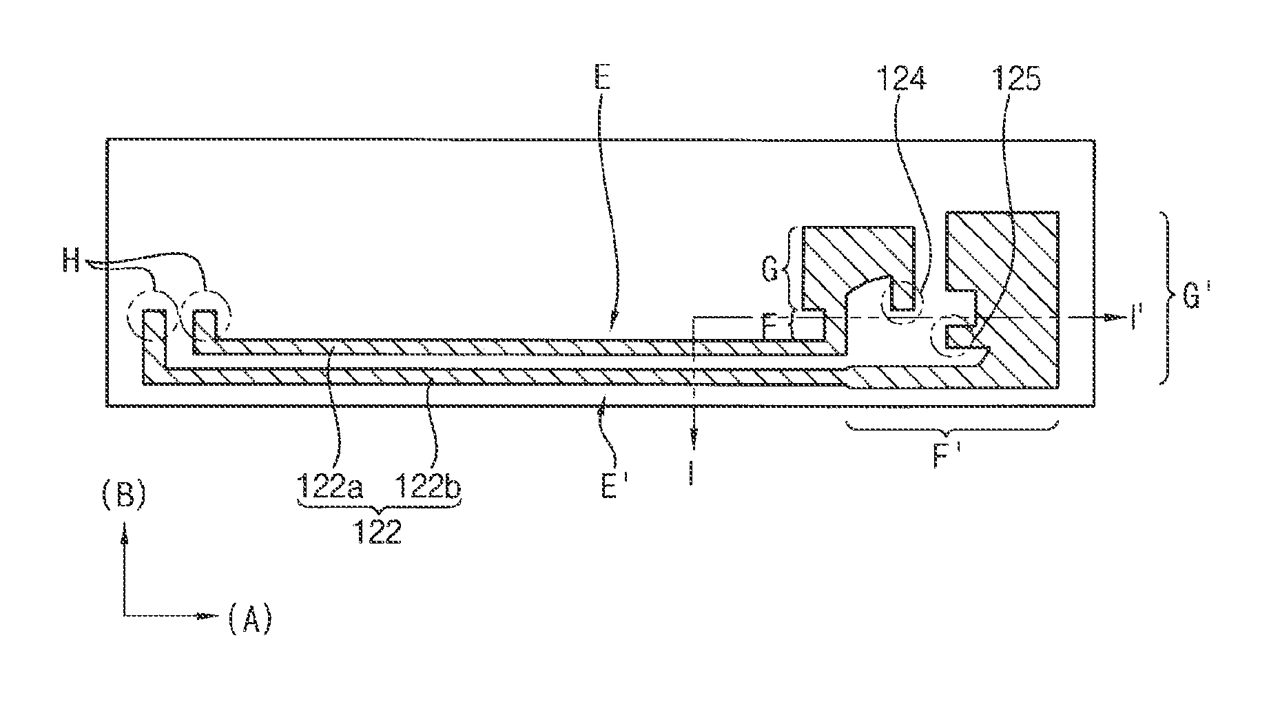
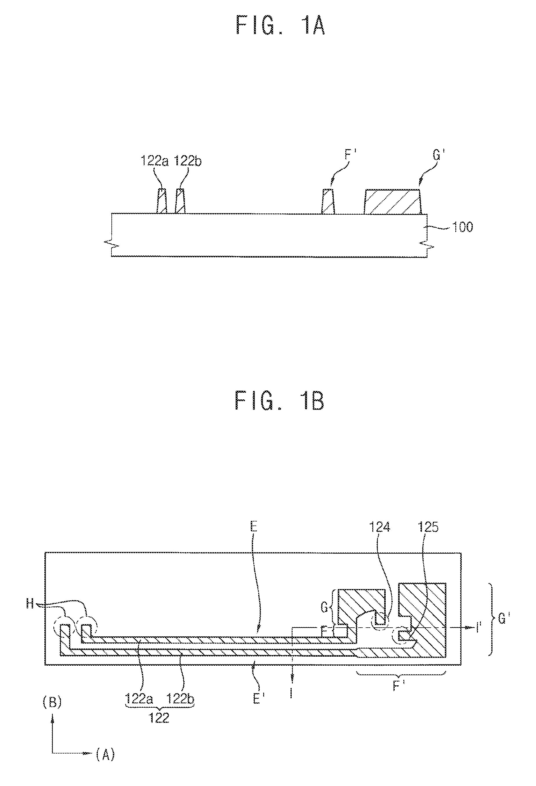
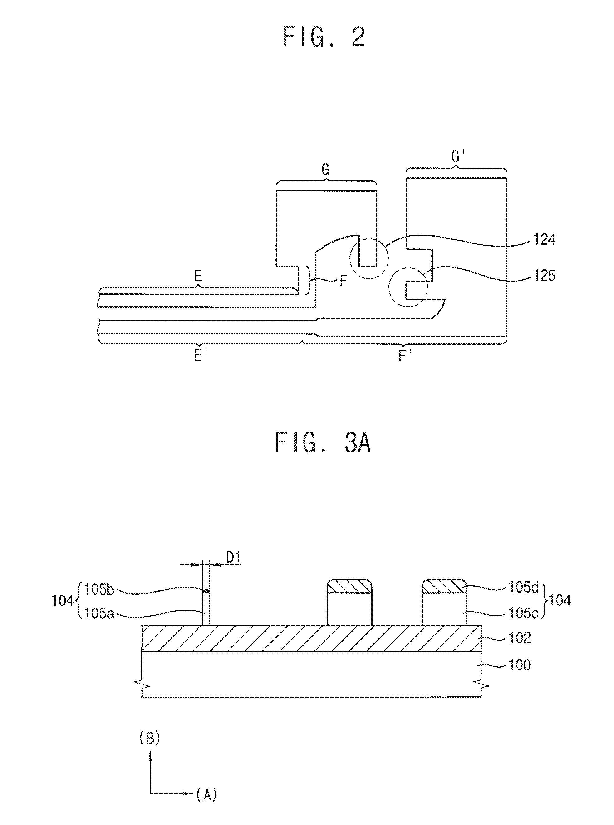
A pattern structure in a semiconductor device includes an extending line and a pad connected with an end portion of the extending line. The pad may have a width that is larger than a width of the extending line. The pad includes a protruding portion extending from a lateral portion of the pad. The pattern structure may be formed by simplified processes and may be employed in various semiconductor devices requiring minute patterns and pads.

Description

CROSS-REFERENCE TO RELATED APPLICATIONS[0001]This application claims the benefit of Korean Patent Application No. 2009-0086808, filed on Sep. 15, 2009 in the Korean Intellectual Property Office, the disclosure of which is incorporated herein by reference in its entirety.BACKGROUND[0002]1. Field of the Invention[0003]Example embodiments of the present general inventive concept relate to pattern structures in semiconductor devices and methods of forming pattern structures in semiconductor devices. More particularly, example embodiments of the present general inventive concept relate to pattern structures including pads and method of forming pattern structures including pads.[0004]2. Description of the Related Art[0005]In the conventional method of manufacturing a semiconductor device, it is very difficult to exactly form a minute pattern having a width below about 40 nm. To form such a minute pattern, a doubling pattern method is typically used. In the double patterning method, a spac...

Claims


Application Information

Patent Timeline
IPC IPC(8): H01L23/528
CPCH01L21/0337H01L21/3081H01L21/31144H01L21/32139H01L21/76802H01L27/11521H01L2924/0002H01L23/528H01L2924/00H10B41/30H01L21/0338H01L21/0334H01L21/76816H01L21/311
Inventor SIM, JAEHWANGMIN, JAEHOLEE, JAEHANKIM, KEONSOO
Owner SAMSUNG ELECTRONICS CO LTD
Why Eureka
Try Eureka