
Thermal analysis apparatus

a technology of thermal analysis and apparatus, which is applied in the direction of instruments, heat measurement, calorimeters, etc., can solve the problems of difficult determination, poor thermal conductivity, and the likelihood of uneven temperature distribution in the window portion, so as to prevent the influence of uneven temperature distribution, stable temperature distribution, and accurate thermal analysis data

Active Publication Date: 2011-03-03
HITACHI HIGH TECH SCI CORP
View PDF2 Cites 17 Cited by
  • Summary
  • Abstract
  • Description
  • Claims
  • Application Information

AI Technical Summary

Benefits of technology

[0011]In view of the above, the present invention has been made in order to solve the problem with the thermal conductivity of the transparent observation window provided to the lid portion of the furnace, and it is therefore an object of the present invention to provide a thermal analysis apparatus which includes a transparent observation window and imaging means that are used for observing a sample state within a furnace, and is capable of obtaining excellent thermal analysis data with less distortion and fluctuation.
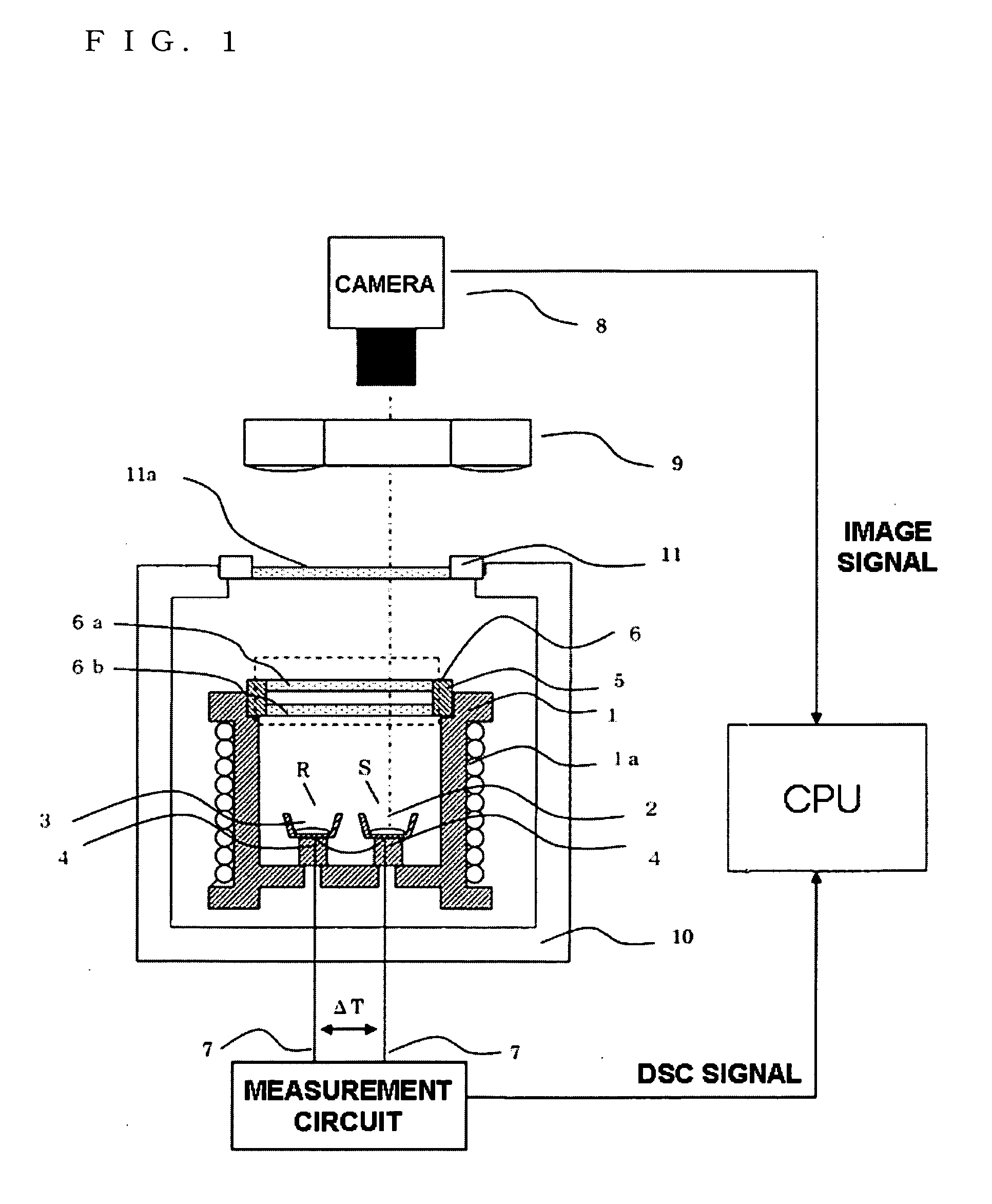
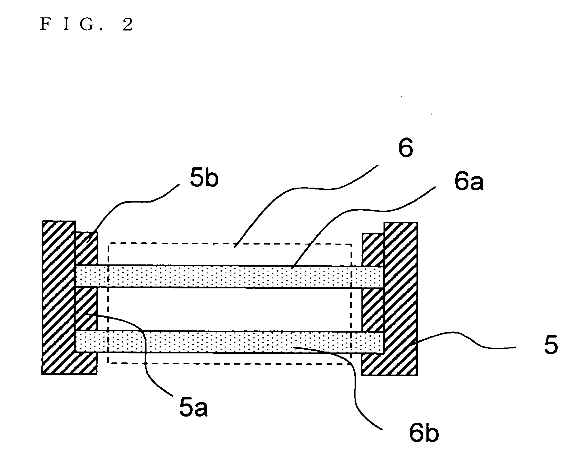
[0013]For the transparent observation window formed in at least the part of the furnace, a transparent material having heat resistance and rigidity, such as quartz glass and borosilicate glass, may be used. The observation window formed of the transparent material includes at least two layers, and hence temperature disturbance due to temperature of gas outside the furnace within the apparatus directly and mainly influences the transparent member of a furnace outer layer that constitutes the transparent observation window. In addition, the heat insulation layer provided between the transparent members produces an effect of preventing the influence of the uneven temperature distribution generated in the above-mentioned transparent member of the furnace outer layer from being spread to the transparent member of a furnace inner layer. Accordingly, the influence of the disturbance on the temperature distribution within the furnace and the temperature distribution of the gas within the furnace may be suppressed to a low level. As a result, a stable temperature distribution is ensured within the furnace because of the smaller influence of the disturbance, and the detection portion for the thermal change, which is installed within the furnace, does not detect the influence of the disturbance as a signal. Thus, stable and accurate detection for a thermal change and imaging of a sample state at the time of the detection are enabled.
[0015]As described above, according to the present invention, the transparent observation window provided to the part of the furnace lid to allow the sample state to be imaged includes at least two layers, and the layer having a heat insulation effect is provided between the transparent members, which reduces the risk that the influence of the temperature disturbance outside the furnace becomes a factor of instability with respect to the temperature within the furnace. As a result, the case where the influence of the temperature disturbance is detected by the detection portion for the thermal change, which is installed within the furnace, is avoided, to thereby build an environment for measuring a thermal change in a sample with no disturbance. As a result, stable and accurate thermal analysis data can be obtained with less distortion and fluctuation.

Problems solved by technology

This enables a change in sample state to be grasped correctly, which is difficult to determine based only on the DSC curve.
Hei 08-327573, the transparent observation window, which is used for observing a sample and is provided to the lid in the upper part of the furnace, is made of quartz glass, and hence the thermal conductivity is poor and uneven temperature distribution is likely to be generated in the window portion due to an influence of disturbance of the environment outside the furnace.
Further, the transparent observation window is formed of one layer, and hence the above-mentioned uneven temperature distribution generated in the observation window may easily be spread to the inside of the furnace, with the result that the influence of the disturbance may easily be imposed on temperature distribution within the furnace and temperature distribution of gas within the furnace.
As a result, the uneven temperature distribution generated by the disturbance of the environmental temperature in the transparent observation window formed of one layer may cause distortion, fluctuation, and the like in the DSC curve.
This leads to a problem that it is difficult to obtain a stable and accurate DSC curve.
However, though the furnace is required to ensure a stable temperature distribution under precise temperature control for a thermal analysis / measurement, the observation window of the furnace lid provided to the upper part of the furnace portion is formed of one layer, which leads to the same problem as in Japanese Patent Application Laid-open No.
Also in Japanese Patent Application Laid-open No. 2001-33410, the transparent material portion formed in the side wall of the sample cylinder is formed of one layer, which leads to the same problem.

Method used


Image

  • Thermal analysis apparatus
  • Thermal analysis apparatus
  • Thermal analysis apparatus

Examples


embodiment

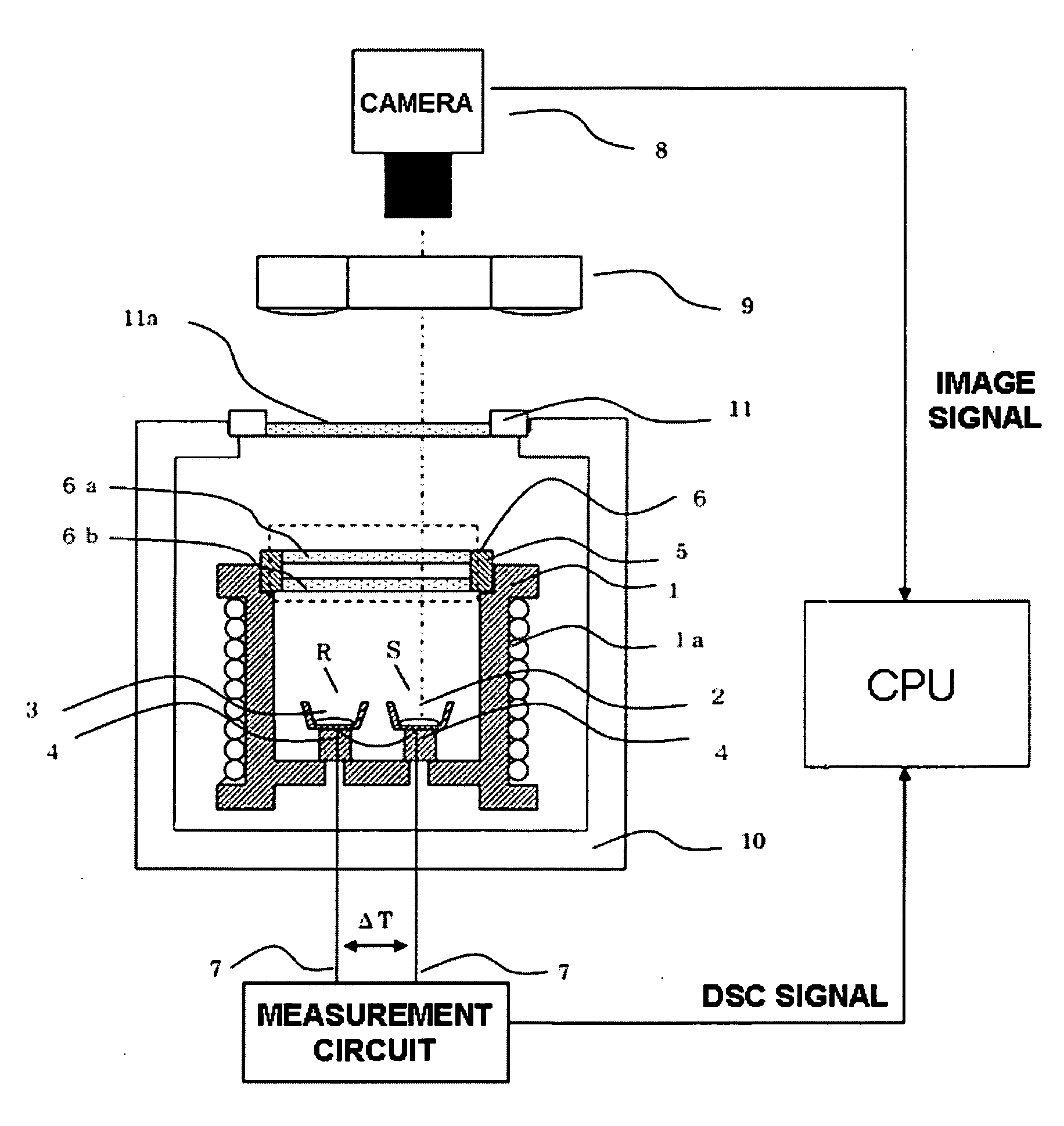
[0022]FIG. 1 illustrates a configuration of a differential scanning calorimeter (DSC) as an example of a thermal analysis apparatus according to the present invention. The differential scanning calorimeter includes a furnace 1 and a heater coil 1a wound therearound. The heater coil 1a is used for heating the furnace 1. Although not illustrated, the furnace 1 has a cover attached therearound so that the heater coils 1a are not exposed. There are arranged, within the furnace 1, a sample holder 2 for receiving a measurement sample and a reference sample holder 3 for receiving a reference sample. The respective holders have thermocouples connected thereto, which constitute differential heat flow detection portions 4 for detecting a temperature difference between the holders. Thermocouple wires 7 extending from the differential heat flow detection portions 4 are connected to a measurement circuit, and detected signals are recorded in the form of a DSC curve after being amplified.

[0023]Th...


PUM

PropertyMeasurementUnit
thermal analysisaaaaaaaaaa
temperatureaaaaaaaaaa
heat quantityaaaaaaaaaa

Abstract

To avoid an influence on measurement accuracy in a case where an observation window for a measurement sample is provided to a thermal analysis apparatus, the influence being imposed by thermal conduction through the observation window, the observation window is formed of layers of transparent members, and a gap layer is provided between the layers, to thereby reduce the thermal conduction. Gas or solid having a high heat insulation property is employed for the gap layer to further enhance a heat insulation property of the observation window. Accordingly, a change due to heating of the measurement sample is visually observed in the thermal analysis apparatus, to thereby obtain a thermal change or a physical change with higher accuracy.

Description

BACKGROUND OF THE INVENTION[0001]1. Field of the Invention[0002]The present invention relates to a thermal analysis apparatus capable of measuring a thermophysical property of a sample, which changes along with a temperature change, and of imaging and displaying the sample.[0003]2. Description of the Related Art[0004]Among the thermal analysis apparatus, a differential scanning calorimeter is a thermal analysis apparatus in which temperatures of a sample and a reference substance received within a furnace are changed based on a constant rate program, and a temperature difference between the sample and the reference substance is detected, thereby measuring the temperature difference to obtain a heat flow difference. There is known an apparatus which is obtained by combining the differential scanning calorimeter as described above with means for imaging the sample within the furnace, and which records an image of a change in sample state as image data along with a change in heat quant...

Claims


Application Information

Patent Timeline
Patent Type & Authority Applications(United States)
IPC IPC(8): G01K17/00G06F15/00G01K1/08G01K7/02
CPCG01N25/4866G01K17/00
Inventor YAMADA, KENTARO
Owner HITACHI HIGH TECH SCI CORP
Learn More