Thermoplastic film, method for producing same, polarizer and liquid crystal display device
- Summary
- Abstract
- Description
- Claims
- Application Information
AI Technical Summary
Benefits of technology
Problems solved by technology
Method used
Image


Examples
first embodiment
(I-1) the Preferable Arrangement
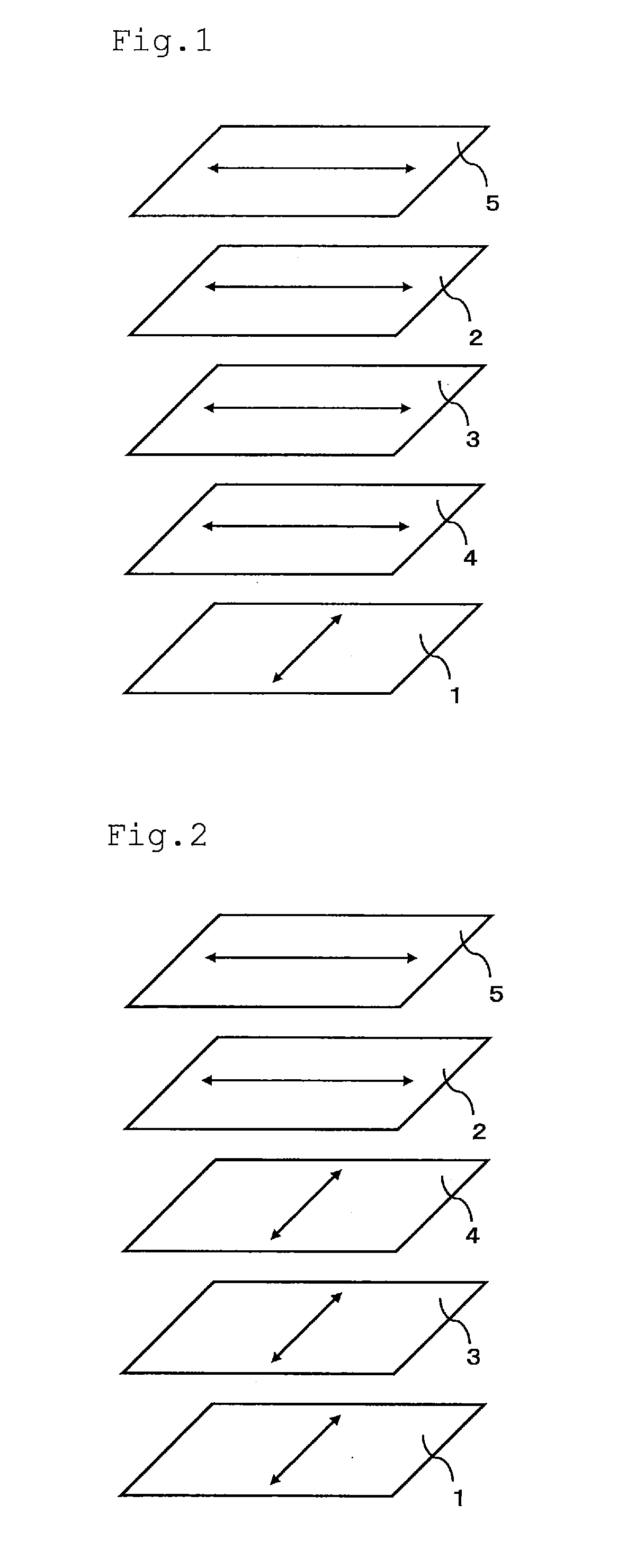
[0332]FIG. 1 shows a diagram exhibiting the first embodiment of the preferable arrangement (referred to as arrangement I-1, hereinafter) of the liquid crystal display device of the present invention. In arrangement I-1, the absorption axis of the polarizing element at the output side and the in-plane slow axis of the liquid crystal of the liquid crystal cell under application of no voltage are disposed at relative positions parallel to each other. The in-plane slow axes of the negative birefringence layer and the positive birefringence layer are disposed at relative positions approximately parallel to each other. It is preferable that the in-plane slow axis of the positive birefringence layer and the in-plane slow axis of the liquid crystal of the liquid crystal cell under application of no voltage are disposed at relative positions approximately parallel to each other, and the negative birefringence layer is disposed at a position closer to the liqui...
second embodiment
(I-2) the Preferable Arrangement
[0335]FIG. 2 shows a diagram exhibiting the second embodiment of the preferable arrangement (referred to as arrangement I-2, hereinafter) of the liquid crystal display device of the present invention. In arrangement I-2, the absorption axis of the polarizing element at the output side and the in-plane slow axis of the liquid crystal of the liquid crystal cell under application of no voltage are disposed at relative positions parallel to each other. The in-plane slow axes of the negative birefringence layer and the positive birefringence layer are disposed at relative positions approximately parallel to each other. It is preferable that the in-plane slow axis of the positive birefringence layer and the in-plane slow axis of the liquid crystal of the liquid crystal cell under application of no voltage are disposed at relative positions approximately perpendicular to each other, and the positive birefringence layer is disposed at a position closer to the...
third embodiment
(II-1) the Preferable Arrangement
[0338]FIG. 3 shows a diagram exhibiting the third embodiment of the preferable arrangement (referred to as arrangement II-1, hereinafter) of the liquid crystal display device of the present invention. In arrangement II-1, the absorption axis of the polarizing element at the output side and the in-plane slow axis of the liquid crystal of the liquid crystal cell under application of no voltage are disposed at relative positions parallel to each other. The in-plane slow axes of the negative birefringence layer and the positive birefringence layer are disposed at relative positions approximately parallel to each other. It is preferable that the in-plane slow axis of the positive birefringence layer and the in-plane slow axis of the liquid crystal of the liquid crystal cell under application of no voltage are disposed at relative positions approximately perpendicular to each other, and the negative birefringence layer is disposed at a position closer to t...
PUM
| Property | Measurement | Unit |
|---|---|---|
| Temperature | aaaaa | aaaaa |
| Temperature | aaaaa | aaaaa |
| Fraction | aaaaa | aaaaa |
Abstract
Description
Claims
Application Information
 - R&D
- Intellectual Property
- Life Sciences
- Materials
- Tech Scout
- Unparalleled Data Quality
- Higher Quality Content
- 60% Fewer Hallucinations
Browse by: Latest US Patents, China's latest patents, Technical Efficacy Thesaurus, Application Domain, Technology Topic, Popular Technical Reports.
© 2025 PatSnap. All rights reserved.Legal|Privacy policy|Modern Slavery Act Transparency Statement|Sitemap|About US| Contact US: help@patsnap.com