
Image Processing Device, Image Processing Method, and Program

a technology of image signal processing and image processing device, which is applied in the direction of image enhancement, radiation controlled devices, instruments, etc., can solve the problems of rgbw type devices, false color more readily occurring, and the amount of incident light to each of the pixels decreases and the s/n ratio increases, so as to achieve a small amount of false color or blurring

Active Publication Date: 2011-03-03
SONY CORP
View PDF14 Cites 62 Cited by
  • Summary
  • Abstract
  • Description
  • Claims
  • Application Information

AI Technical Summary

Benefits of technology

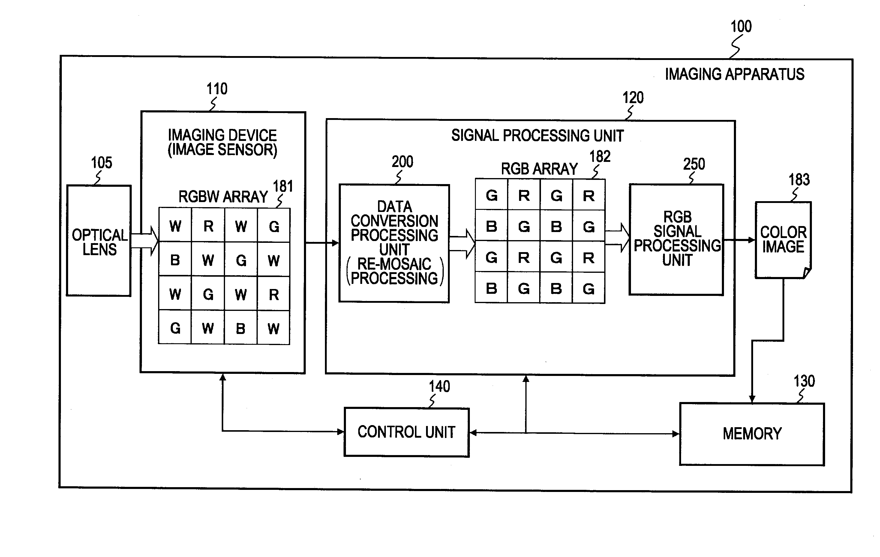
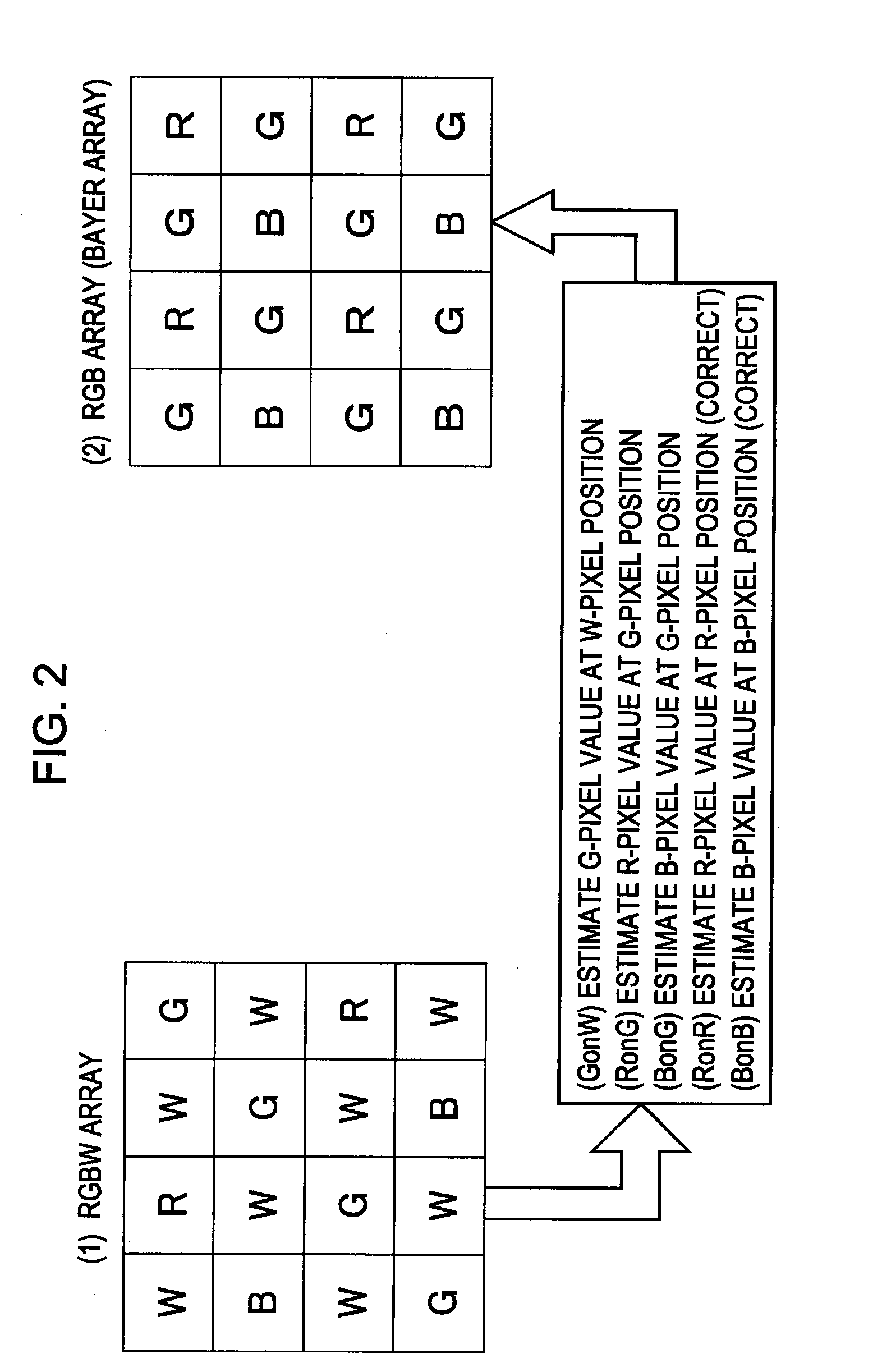
[0011]It has been found desirable to provide, with regard to color image generating processing in which data acquired by an imaging device (image sensor) having white (W) such as an RGBW type color filter, an image processing device, image processing method, and program, realizing generating of high-quality color image with little false color or blurring.
[0024]The image processing method may further include the step of: analyzing, with an edge detecting unit, of output signals from an imaging device having an RGBW array which includes RGB pixels and white (W) pixels, and generating of edge information including edge intensity information corresponding to each pixel; with the converting including RGB signal value determining further including calculating of blurring-uncorrected RGB signals (Rl, Gl, Bl) which are signals to which blurring correction processing is not applied, and performing determining processing of RGB signals values making up an RGB array or color image by blending processing of the blurring-corrected RGB signals and the blurring-uncorrected RGB signals; and the RGB signal value determining being performed by executing blending processing in which at pixel positions where determination is made that edge intensity is great from the edge information, the blend ratio of blurring-corrected RGB signals is increased, and at pixel positions where determination is made that edge intensity is small, the blend ratio of blurring-uncorrected RGB signals is increased.
[0027]The program may further include the step of: analyzing, with an edge detecting unit, of output signals from an imaging device having an RGBW array which includes RGB pixels and white (W) pixels, and generating of edge information including edge intensity information corresponding to each pixel; with the converting including RGB signal value determining further including calculating of blurring-uncorrected RGB signals (Rl, Gl, Bl) which are signals to which blurring correction processing is not applied, and performing determining processing of RGB signals values making up an RGB array or color image by blending processing of the blurring-corrected RGB signals and the blurring-uncorrected RGB signals; and with the RGB signal value determining being performed by executing blending processing in which at pixel positions where determination is made that edge intensity is great from the edge information, the blend ratio of blurring-corrected RGB signals is increased, and at pixel positions where determination is made that edge intensity is small, the blend ratio of blurring-uncorrected RGB signals is increased.

Problems solved by technology

As of recent, imaging devices (image sensors) have come to have finer pixel configurations, and accordingly there has arisen the problem that the amount of incident light to each of the pixels decreases and the S / N ratio increases.
However, RGBW type devices have the following problems.
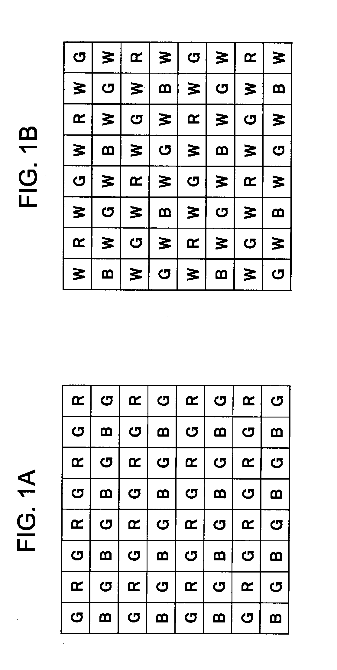
Consequently, in the event that data acquired with the RGBW array type device shown in FIG. 1B is used in color image generating processing, there is a problem that false color more readily occurs as compared with the RGB array shown in FIG. 1A.
Also, the white (W) wavelength component includes all wavelength components of R, G, and B, so using an optical lens with great chromatic aberration can result in poorer light collection as compared with monochromatic arrangements, leading to deterioration in resolution.
This problem becomes more marked as pixel configurations become finer.
As a technique to prevent deterioration in resolution due to chromatic aberration of the optical lens, combining lenses with different refractive indexes effectively prevents chromatic aberration from occurring, but this leads to a new problem of increased costs, since the number of lenses increases.
This configuration also leads to a problem in that false color due to deterioration of the sampling rate of the RGB components described above is more marked.
However, near the edges, the above assumption of the color ratio being generally constant in local regions and of strong color correlation does not hold.
Accordingly, there is a problem that false color readily occurs near the edges.

Method used


Image

  • Image Processing Device, Image Processing Method, and Program
  • Image Processing Device, Image Processing Method, and Program
  • Image Processing Device, Image Processing Method, and Program

Examples


Embodiment Construction

[0059]The image processing device, image processing method, and program, according to an embodiment of the present invention, will be described below with reference to the drawings. Note that description will proceed as follows.[0060]1. Overview of Processing[0061]2. Configuration Example of Imaging Apparatus and Image Processing Device, and Processing Example[0062]3. Details of Processing with Data Conversion Processing Unit[0063]3-1. About Processing with Edge Detection Unit[0064]3-2. About Processing with Blurring Correction Processing Unit[0065]3-3. About Processing with Color Correlation Re-mosaic Processing Unit (data conversion unit)[0066]4. Embodiment of Performing Demosaic Processing on RGBW Array Signals[0067]5. Advantages of Processing According to Embodiments

1. Overview of Processing

[0068]First, the overview of processing which an image processing device such as the imaging apparatus according to an embodiment of the present invention executes will be described with refe...


PUM


Abstract

An image processing device includes: a blurring correction processing unit configured to perform blurring correction processing on output signals of an imaging device having an RGBW array which includes RGB pixels and white (W) pixels, and generate blurring-corrected signals corresponding to each pixels; and a data conversion unit configured to convert the RGBW array into an RGB array; wherein the data conversion unit executes processing of generating blurring-corrected RGB signals (Rd, Gd, Bd) which are blurring-corrected signals corresponding to RGB that have been estimated from blurring-corrected signals generated by the blurring correction processing unit, and applying the blurring-corrected RGB signals (Rd, Gd, Bd) to determine RGB signals values configuring an RGB array.

Description

BACKGROUND OF THE INVENTION[0001]1. Field of the Invention[0002]The present invention relates to an image processing device, and image processing method, and a program, and more particularly relates to an image processing device, and image signal processing method, and a program, for performing signal processing as to output of an imaging device having an RGBW array.[0003]2. Description of the Related Art[0004]Imaging devices (image sensors) used for imaging apparatuses, for example, have a structure wherein a color filter, which transmits specific wavelength component light (R, G, B) in increments of pixels, is applied to the surface thereof. For example, a filter having an RGB array such as shown in FIG. 1A is used. With color image generating processing using output signals of an imaging device, processing is performed for reproducing color components to be used, in sets of multiple pixels. While there are various types of color arrays for color filters, the Bayer array shown in ...

Claims


Application Information

Patent Timeline
IPC IPC(8): H04N5/228
CPCH04N5/217H04N9/045H04N5/23248H04N23/81H04N23/68H04N25/133H04N25/135H04N23/843H01L27/146H04N23/70H04N23/12G06T5/73
Inventor TACHI, MASAYUKI
Owner SONY CORP
Learn More