Ink discharge apparatus

Active Publication Date: 2011-03-03
BROTHER KOGYO KK
View PDF4 Cites 10 Cited by
  • Summary
  • Abstract
  • Description
  • Claims
  • Application Information

AI Technical Summary

Benefits of technology

[0010]The present inventors have found out the following fact. That is, especially during the cap release operation in which a cap formed with no atmospheric air communication hole is separated from the nozzle surface, an ink bridge, which is continuous to bridge the cap and the nozzle surface, is firstly formed, and then the ink is separated into those disposed on the nozzle surface side and the cap side so that the ink bridge is cut. Further, the present inventors have found out the fact that the mixing of the dark color ink into the nozzles for the pale color ink can be greatly mitigated by controlling the position at which the ink bridge is formed.
[0011]The present invention has been made in order to solve the problem as described above, an object of which is to provide an ink discharge apparatus provided with a plurality of nozzles for discharging inks of different colors including a dark color ink and a pale color ink paler than the dark color ink, wherein it is possible to reduce the advance of any ink subjected to the color mixture into the nozzles for the pale color ink after the purge operation.
[0020]In the ink discharge apparatus constructed as described above, the ink bridge, which is formed between the cap and the nozzle surface when the cap is separated from the nozzle surface of the discharge head after the completion of the purge operation, is formed in the area of the nozzle surface in which the nozzle array for the dark color ink is formed or in the area which is disposed in the vicinity thereof. When the ink bridge is formed in the areas as described above, then the flow, which is directed toward the nozzle array for the dark color ink, is generated in the ink on the nozzle surface, and it is possible to suppress the dark color ink from flowing toward the pale color ink paler than the dark color ink on the nozzle surface. Accordingly, it is possible to reduce the advance of the ink of any other color into the nozzles, especially into the nozzles for the pale color ink after the completion of the purge operation, and it is possible to reduce the color mixture of the inks in the nozzles of the discharge head. Owing to the reduction of the color mixture of the inks in the nozzles of the discharge head, the number of times of the flashing is not uselessly increased in the flashing operation, and it is possible to suppress the increase in the ink consumption amount.

Problems solved by technology

However, the ink, which has been already caught into the discharge head, cannot be removed by the wipe operation.
Therefore, in such a situation, the jetting amount of the ink to be discharged in the flashing operation is increased, i.e., the amount of the ink, which is used for any purpose other than the original purpose of the printing or the like, is increased, and thus the ink is uselessly consumed.
In particular, if the dark color ink such as the black is mixed into the nozzles for the pale color ink (light color ink) such as the yellow, then a resultant mixed color (color mixture) ink has a color darker than the pale color ink, and the harmful influence, which is exerted on the printing quality, is more serious.

Method used


Image

  • Ink discharge apparatus
  • Ink discharge apparatus
  • Ink discharge apparatus

Examples


first embodiment

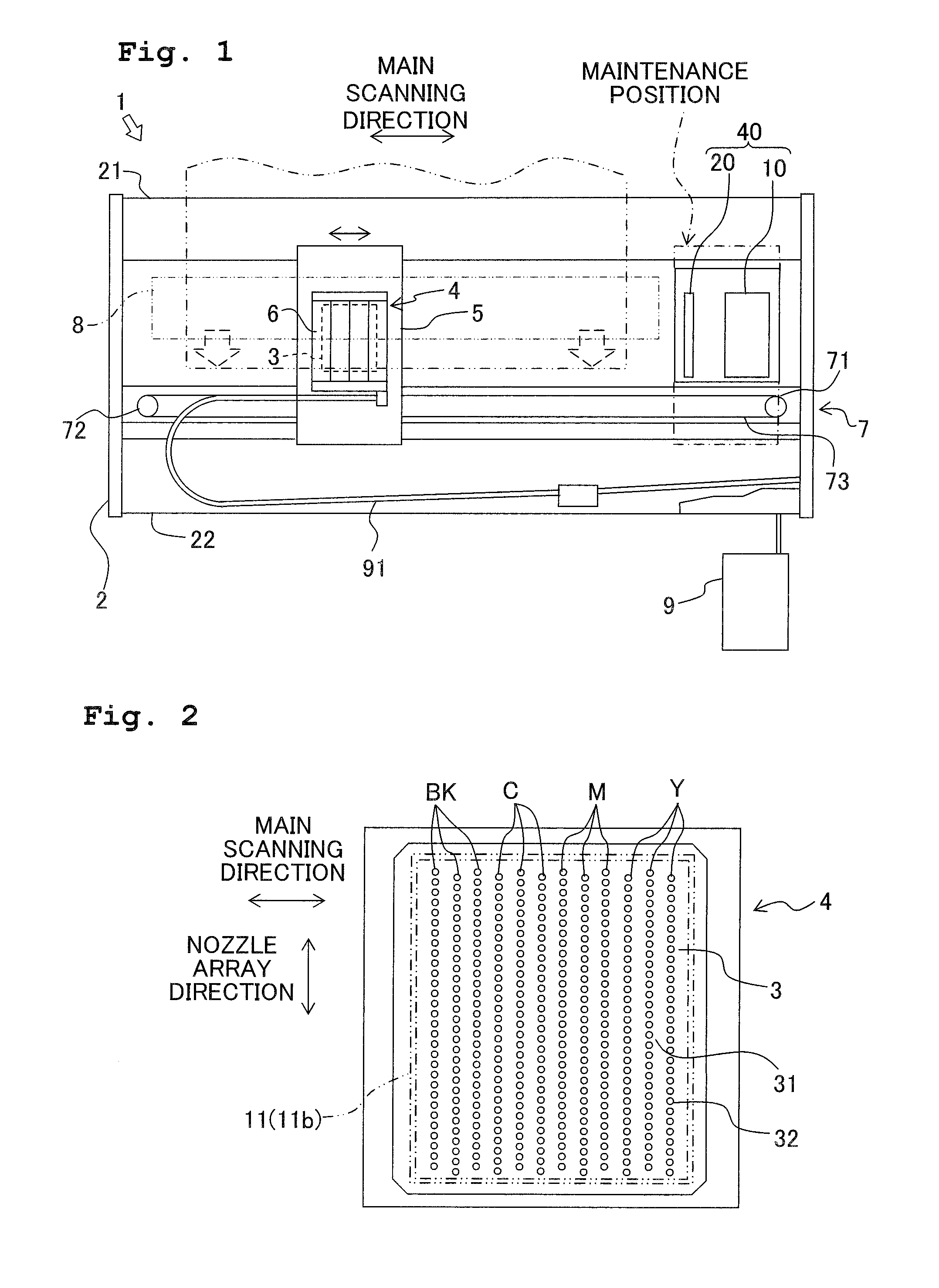
[0036]An explanation will be made below with reference to the drawings as exemplified by an ink-jet type color printer apparatus (printer 1) as the ink discharge apparatus according to a first embodiment by way of example. The printer 1 shown below is the ink-jet type color printer based on the ink-jet system in which an image is printed by discharging inks of four colors (black (Bk), yellow (Y), cyan (C), and magenta (M)) to a paper as a recording medium.

[0037]As shown in FIG. 1, the printer 1 includes a frame (body frame) 2, a carriage 5 which is provided on the frame 2 so that the carriage 5 is reciprocatively movable in the main scanning direction (left-right direction as viewed in FIG. 1), and a discharge head unit 4 which is carried on the carriage 5. A platen 8 is provided in the frame 2. The recording medium is transported in the frontward direction (direction toward the front as viewed in FIG. 1) by means of, for example, an unillustrated feed roller on the platen 8.

[0038]T...

first modified embodiment

[0067]In the foregoing description, the pivot support shaft 45, which is formed at one end of the cap 11, is restricted by the bearing portion 43c of the cap holder 13. However, the present teaching is not limited thereto. For example, as shown in FIG. 8, the following arrangement is also available. That is, locking projections 246 are formed at both ends of a cap 211 respectively. Projection-shaped or protruding stoppers 243b, which are engageable with the locking projections 246, are provided at portions of a substantially box-shaped cap holder 243 opposed to the both ends of the cap 211 respectively. In this arrangement, the stopper 243b, which is disposed on the left side shown in FIG. 8 (on the side near to the nozzles for the black ink), is formed at a position (position near to the nozzle surface 31) higher than that of the stopper 243b which is disposed on the right side shown in FIG. 8 (on the side near to the nozzles for the yellow ink).

[0068]When the cap holder 243 is pro...

second modified embodiment

[0070]As shown in FIG. 9A, the following arrangement is also available. That is, pivot support shafts 345 are formed at both ends of a substantially box-shaped cap 311 in the extending direction of the nozzle array. The cap 311 is rotatably supported by bearing portions 343c of a cap holder 343 so that the cap 311 is rotatable in the direction of the arrow shown in FIG. 9B. In this arrangement, as shown in FIG. 9B, the position, at which the coil spring 344 urges the cap 311, is arranged while being deviated from the pivot support shafts 345 in the direction perpendicular to the nozzle array extending direction. Specifically, the coil spring 344 urges the cap 311 at the position nearer to the nozzle array for the dark color ink as compared with the pivot support shafts 345 in the perpendicular direction. Therefore, when the cap holder 343 is moved downwardly, the cap 311 is inclined so that one end portion 311L (the other end portion), which is disposed on the side near to the nozzl...


PUM


Abstract

An ink discharge apparatus is provided, including a discharge head which has a nozzle surface formed with a first nozzle for discharging an ink of a first color and a second nozzle for discharging an ink of a second color darker than the first color; a cap; a sucking mechanism which performs suction for a space in the cap; a moving mechanism which positions the cap at a capping position and at a retracted position; and a purge control mechanism which controls the moving mechanism so that the cap is separated from the nozzle surface while allowing a second distance between the cap and an area near the second nozzle to be smaller than a first distance between the cap and an area near the first nozzle after completion of a purge operation.

Description

CROSS REFERENCE TO RELATED APPLICATION[0001]The present application claims priority from Japanese Patent Application No. 2009-199287, filed on Aug. 31, 2009, the disclosure of which is incorporated herein by reference in its entirety.BACKGROUND OF THE INVENTION[0002]1. Field of the Invention[0003]The present invention relates to an ink discharge apparatus which forms an image on a recording medium by discharging fine ink droplets from nozzles toward the recording medium such as a paper or the like.[0004]2. Description of the Related Art[0005]Conventionally, an ink discharge apparatus is known, which is exemplified by a printer apparatus based on the ink-jet system for forming an image on a recording medium by discharging inks toward the recording medium such as a paper or the like. Such an ink discharge apparatus includes a discharge head provided with nozzles for discharging the inks and ink cartridges accommodating the inks. The ink discharge apparatus discharges the inks supplied...

Claims


Application Information

Patent Timeline
IPC IPC(8): B41J2/165
CPCB41J2/16532B41J2/16511
Inventor NISHIDA, KATSUNORI
Owner BROTHER KOGYO KK
Why Eureka
Try Eureka