
System For Efficient Energy Generation

a technology of energy generation and energy storage, applied in the direction of electric vehicles, dynamo-electric machines, electrical apparatus, etc., can solve the problems of inability to regenerate themselves, limited solutions,

Inactive Publication Date: 2011-03-03
ROSS JONATHAN
View PDF15 Cites 21 Cited by
  • Summary
  • Abstract
  • Description
  • Claims
  • Application Information

AI Technical Summary

Benefits of technology

[0009]In another embodiment of a system according to another embodiment of the present disclosure, the drive shaft may further comprise a flywheel. In this manner, the flywheel may be rotated by the drive shaft in order to cause the flywheel to rotate at an optimum rotational frequency. The rotational frequency may be measured by a tachometer, which may supply a signal to a motor control to activate or deactivate the electric motor.
[0010]The current invention can recharge a battery pack without the need for fuel (fossil or otherwise), win

Problems solved by technology

Previous solutions are limited in that they are unable to regenerate themselves without the use of external energy sources such as fossil fuel, sun, wind, or water.

Method used


Image

  • System For Efficient Energy Generation
  • System For Efficient Energy Generation
  • System For Efficient Energy Generation

Examples


Embodiment Construction

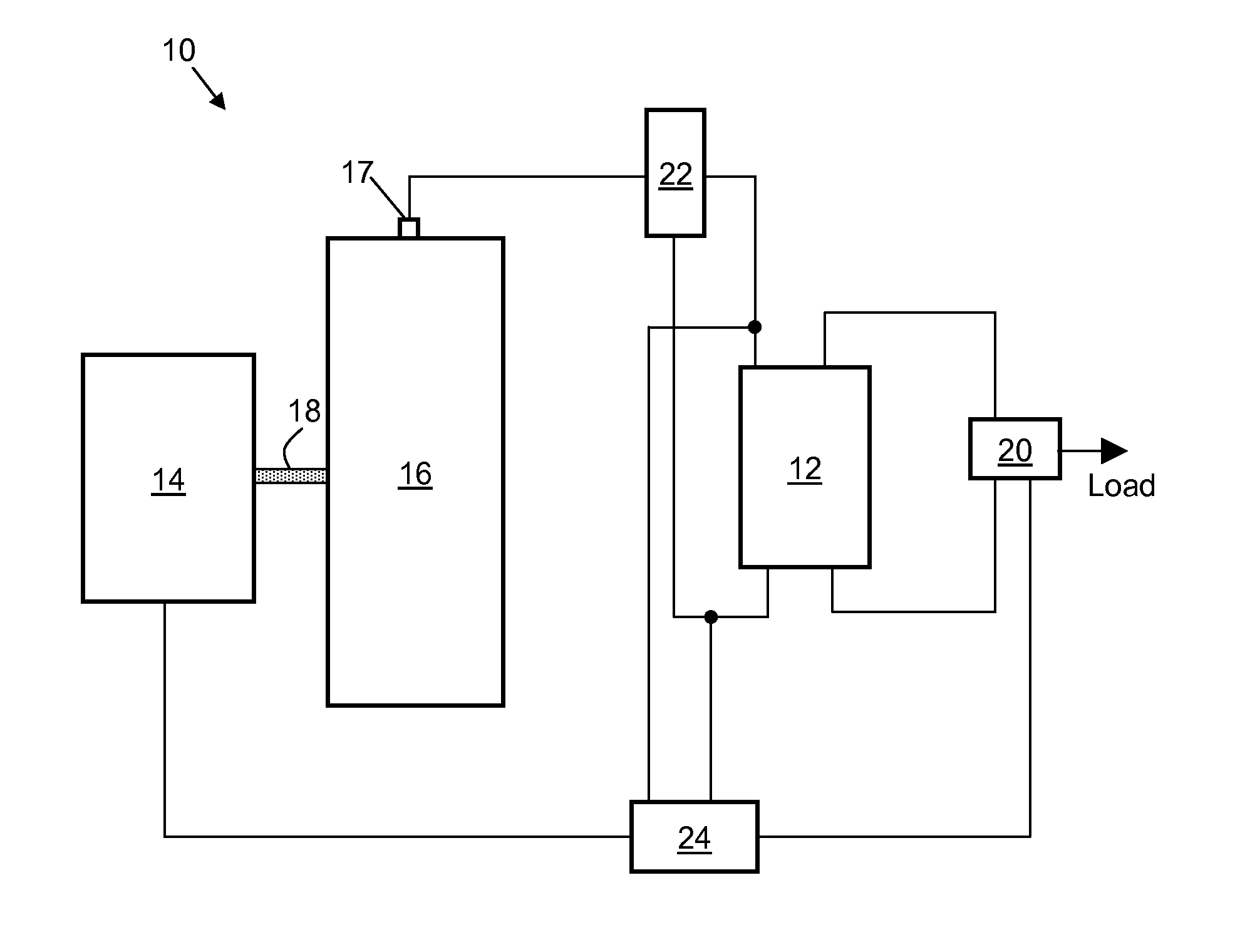
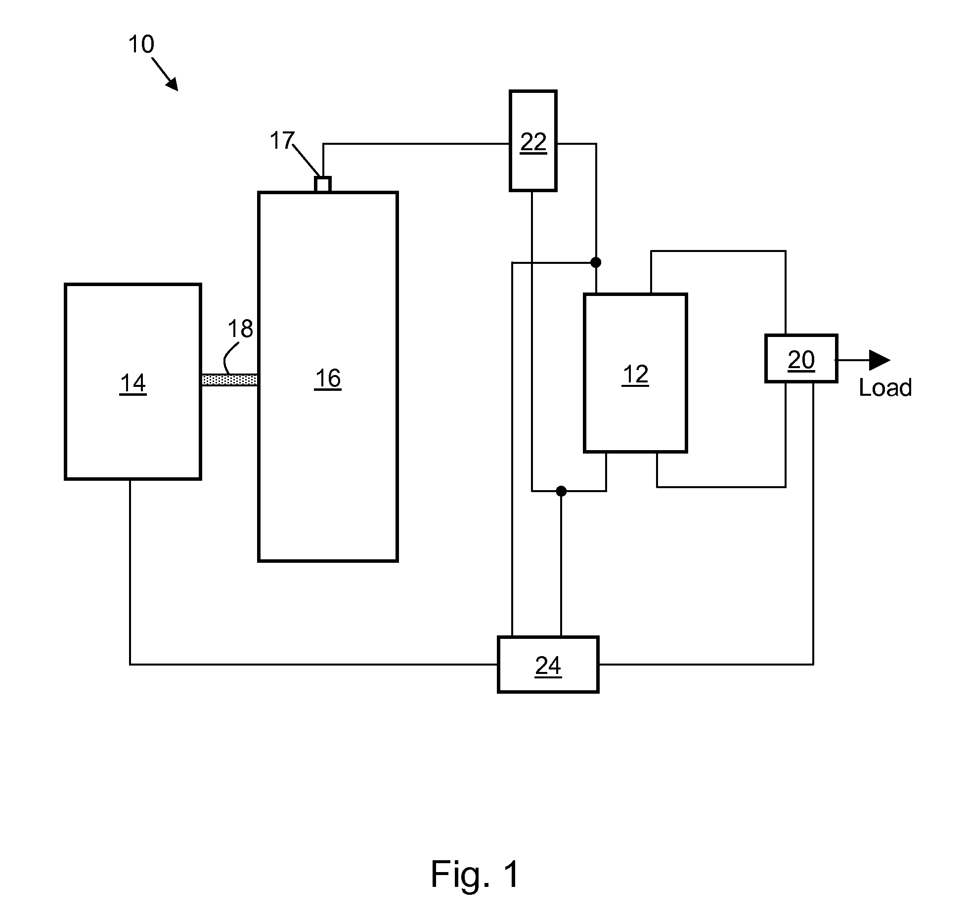
[0018]FIG. 1 depicts a system 10 for generating energy according to the present disclosure. A power source 12 (depicted as a battery in FIG. 1), which is capable of supplying energy in the form of electricity, is provided. Power source 12 is electrically connected to an electric motor 14. In this way, power source 12 provides electrical energy to electric motor 14. The electric motor 14 is thus energized and will cause a drive shaft 18 of the electric motor 14 to rotate about a longitudinal axis.

[0019]Drive shaft 18 is mechanically connected to an electric generator 16. Electric generator 16 is capable of converting the rotation of drive shaft 18 (mechanical energy) into electrical energy. The generated electrical energy is provided to electrical contacts of the electric generator. A load (not shown) may be electrically connected to the electrical contacts of the electric generator 16. As such, the load may receive the electrical energy generated by electric generator 16.

[0020]Power...


PUM


Abstract

A system for generating energy may comprise a power source capable of supplying energy in the form of electricity to an electric motor. The electric motor is energized by the power source and will cause a drive shaft to rotate. The drive shaft is mechanically connected to an electric generator capable of converting the rotation of the drive shaft into electrical energy. A load may be electrically connected to the electric generator, such that the load may receive the electrical energy generated by electric generator.

Description

CROSS-REFERENCE TO RELATED APPLICATION[0001]This application claims the benefit of priority to U.S. provisional patent application Ser. No. 61 / 231,851, filed on Aug. 6, 2010, now pending, the disclosure of which is incorporated herein by reference.FIELD OF THE INVENTION[0002]The present invention relates generally to generating energy, and in particular, to efficiently generating energy using a mechanical linkage.BACKGROUND OF THE INVENTION[0003]The need for a clean, renewable source of electrical power is readily apparent today. One of the many pressing needs is in the realm of residential domestic power generation. Many of the “off grid” systems rely on a battery pack, supplying power to the home via an inverter, and recharged by a fuel fed generator, wind generator, solar panels, or water generator.[0004]Previous solutions are limited in that they are unable to regenerate themselves without the use of external energy sources such as fossil fuel, sun, wind, or water.BRIEF SUMMARY ...

Claims


Application Information

Patent Timeline
IPC IPC(8): H02P9/04H02K47/14H02K53/00
CPCH02K53/00
Inventor ROSS, JONATHAN
Owner ROSS JONATHAN
Learn More