
Light-Emitting Diode With High Color-Rendering Index

Inactive Publication Date: 2011-03-03
HIGH POWER LIGHTING CORP
View PDF3 Cites 2 Cited by
  • Summary
  • Abstract
  • Description
  • Claims
  • Application Information

AI Technical Summary

Benefits of technology

[0004]A primary object of the present invention is to provide an LED with high color-rendering index, so as to emit warm white light.

Problems solved by technology

Therefore, the white-light LED 6 actually fails to achieve the claimed white-light effect.

Method used


Image

  • Light-Emitting Diode With High Color-Rendering Index
  • Light-Emitting Diode With High Color-Rendering Index
  • Light-Emitting Diode With High Color-Rendering Index

Examples


Embodiment Construction

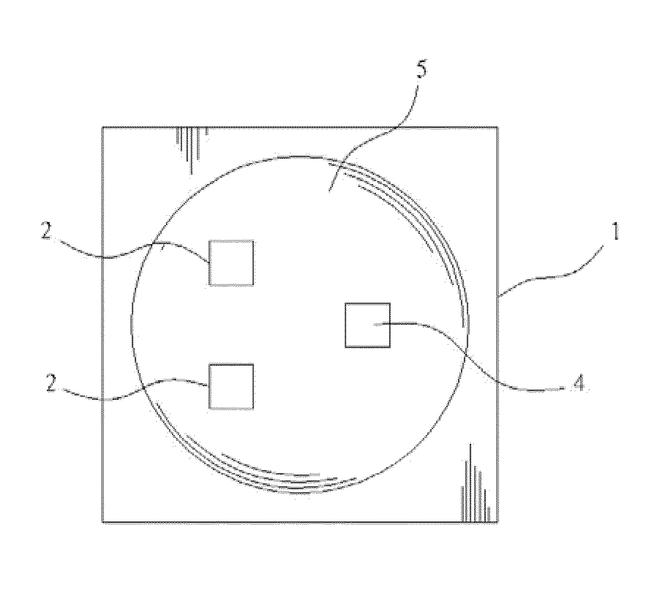
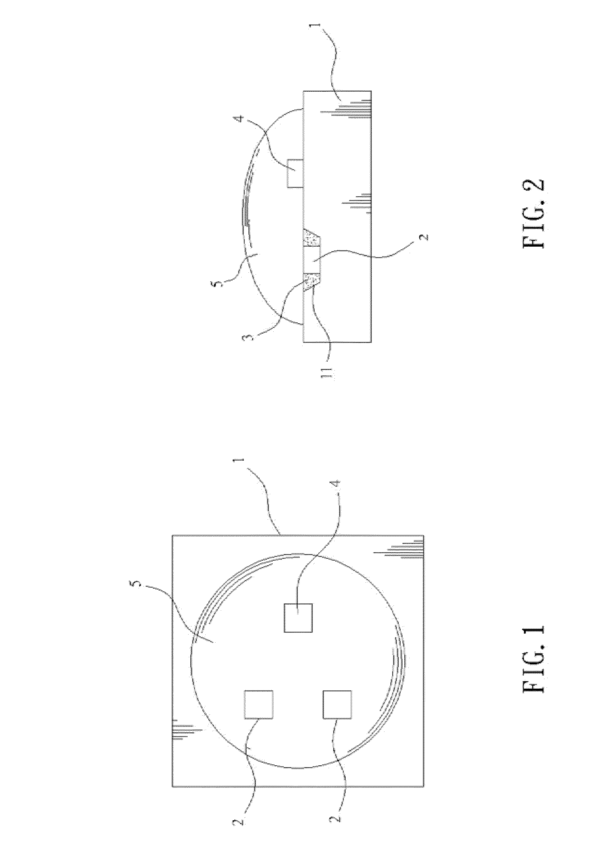
[0011]Please refer to FIGS. 1 and 2 that are sectioned top and side views, respectively, of a light-emitting diode (LED) with high color-rendering index according to a preferred embodiment of the present invention. As shown, the LED with high color-rendering index according to the present invention includes a substrate 1, a plurality of first chips 2, a plurality of fluorescent glues 3, at least one second chip 4, and a light-transmittable layer 5.

[0012]The substrate 1 is provided on one face with a plurality of recesses 11, and can be made of a heat-radiating material, such as an aluminum material, a copper material, etc.

[0013]The first chips 2 each are individually disposed in one of the plurality of recesses 11 on the substrate 1, and the first chips 2 are blue-light chips for emitting blue light.

[0014]The fluorescent glues 3 are separately filled in the recesses 11 on the substrate 1, and each include at least yellow fluorescent powder and green fluorescent powder.

[0015]The seco...


PUM


Abstract

A light-emitting diode (LED) with high color-rendering index includes a substrate being provided on one face with a plurality of recesses; a plurality of first chips being separately disposed in the recesses and adapted to emit blue light; a plurality of fluorescent glues being separately filled in the recesses; at least one second chip being disposed on the substrate at a predetermined position to electrically connect to the first chips, and adapted to emit red light; and a light-transmittable layer provided on the substrate to protectively cover the first chips, the fluorescent glues, and the second chip. The blue light emitted from the first chips and the yellow or green light from the fluorescent glues are mixed first, and the produced light is then further mixed with the red light emitted from the second chip to produce warm white light, which is then projected through the light-transmittable layer.

Description

FIELD OF THE INVENTION[0001]The present invention relates to a light-emitting diode (LED) with high color-rendering index, and more particularly to an LED capable of emitting warm white light by mixing light produced by first chips and fluorescent glues with light from second chips and therefore having high color-rendering index.BACKGROUND OF THE INVENTION[0002]A conventional white-light light-emitting diode (LED) 6, as shown in FIG. 3, includes a printed circuit board 61 being provided with at least one recess 611; a light emitting element 62 being fixed in the recess 611; and a first colloidal material 63 being filled in the recess 611. The light emitting element 62 is adapted to emit blue light, and the first colloidal material 63 includes at least one type of yellow fluorescent powder. With these arrangements, the blue light emitted from the light emitting element 62 interacts with the yellow fluorescent powder in the first colloidal material 63 to produce desired white light.[0...

Claims


Application Information

Patent Timeline
IPC IPC(8): H01L27/15
CPCH01L33/50H01L25/0753H01L2924/0002H01L2924/00
Inventor WEI, CHIH-HUNGWU, MING-CHANGWU, JOHNNY
Owner HIGH POWER LIGHTING CORP
Learn More