
System and Method for Refilling an Electrolyzer Tank from a Water Reservoir

a technology of electrolyzer and water reservoir, which is applied in the direction of electrolysis components, instruments, optics, etc., can solve the problems of reducing reliability and efficiency below 100%, and achieve the effects of maintaining electrolyzer energy efficiency, high operational reliability and convenient long-term operation

Inactive Publication Date: 2011-03-03
SMEDLEY STUART I
View PDF2 Cites 12 Cited by
  • Summary
  • Abstract
  • Description
  • Claims
  • Application Information

AI Technical Summary

Benefits of technology

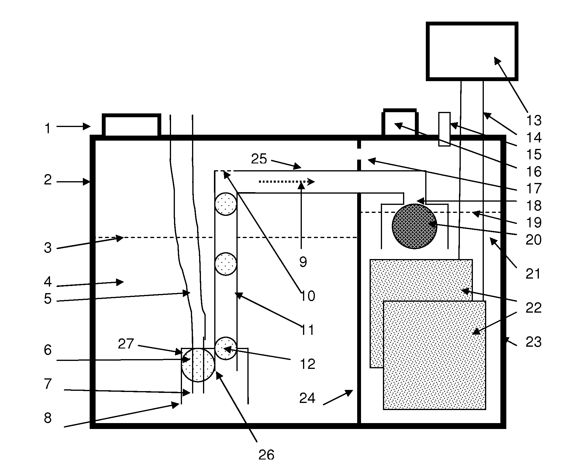
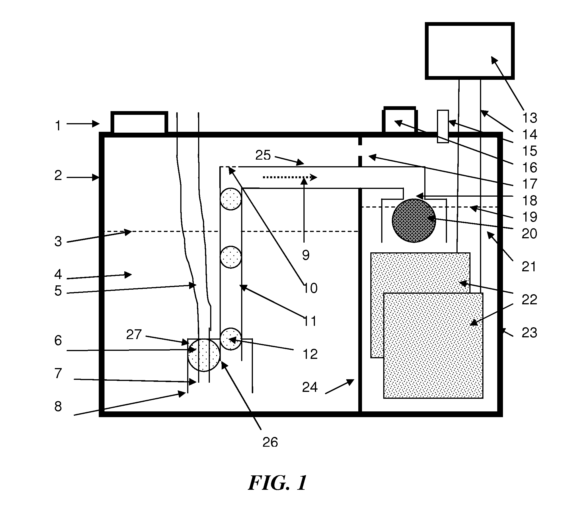
The present invention is about systems and methods for refilling an electrolyzer tank from a water reservoir. The invention includes an electrolysis chamber for producing hydrogen and oxygen, a water reservoir containing make-up water, and a check valve that opens only when the electrolyte level drops to a predetermined level. The invention also includes a gas lift pump with electrodes immersed in the make-up water, which creates bubbles to transport the make-up water to the electrolysis chamber to maintain a desired concentration of the electrolyte during the production of hydrogen and oxygen. The method of the invention ensures a constant concentration of the electrolyte in the water electrolyzer during electrolysis of water.

Problems solved by technology

In practice, however, the efficiency is below 100% because the driving voltage is always greater than 1.23 V.
However, the introduction of electro-mechanical level detectors, valves and pumps can severely reduce reliability, especially when exposed to the harsh environment experienced by devices operating large diesel engines such as long haul trucks, bull dozers, cranes, etc.

Method used


Image

  • System and Method for Refilling an Electrolyzer Tank from a Water Reservoir
  • System and Method for Refilling an Electrolyzer Tank from a Water Reservoir

Examples


Embodiment Construction

[0051]The following disclosure presents an exemplary embodiment of the invention for refilling an electrolyzer tank from a water reservoir. The invention provides a highly reliable, robust and passive control system (and related methods) for maintaining electrolyte level and electrolyte concentration within an electrolyzer tank. This technology rectifies the limitations of prior fluid level control systems, particularly those employed in water electrolyzers designed for use with internal combustion engines. Using the technology of the present invention, an electrolyzer may be optimized for efficiency and operational life.

[0052]Referring to FIG. 1, an exemplary embodiment of the invention is depicted in the form of a schematic for a water electrolyzer. In normal operation, a container 2 holds an amount of water 4, the free surface of which is labeled 3 and container 23 holds an amount of electrolyte 21, the free surface of which is 19. In one embodiment, containers 2 and 23 may be fo...


PUM

PropertyMeasurementUnit
forceaaaaaaaaaa
concentrationaaaaaaaaaa
poweraaaaaaaaaa

Abstract

A system for controlling electrolyte level and concentration within a water electrolyzer includes an electrolysis chamber containing electrolyte for production of hydrogen and oxygen, a water reservoir containing make-up water and separated from the electrolysis chamber through a check valve that opens only when electrolyte level drops to a predetermined level, and a gas lift pump within the water reservoir connected to the electrolysis chamber through the check valve and having electrodes immersed in the make-up water. Energization of the electrodes creates bubbles that transport the make-up water to the electrolysis chamber to maintain a desired concentration of the electrolyte during the production of hydrogen and oxygen.

Description

[0001]This application claims priority to U.S. Provisional Application 61 / 236,828, which was filed on Aug. 25, 2009 and which is fully incorporated herein by reference.BACKGROUND OF THE INVENTION[0002]1. Field of the Invention[0003]The present invention relates generally to electrolyzer systems, and more specifically to systems for controlling fluid level within an electrolyzer, and most specifically to a system and method for maintaining electrolyte level and concentration within a water electrolyzer tank.[0004]2. Description of Related Art[0005]The recovery of hydrogen and oxygen gas by means of electrolysis of water has been practiced for over a century. More recently, water electrolyzers have been used for the purpose of generating and supplying a small stream of hydrogen and oxygen gas as a fuel supplement to internal combustion engines. The hydrogen / oxygen gas stream is usually only a fraction of a percent of the intake combustion air flow but evidence has been presented to sh...

Claims


Application Information

Patent Timeline
Patent Type & Authority Applications(United States)
IPC IPC(8): C25B1/04C25B9/00
CPCC25B1/04C25B9/00Y02E60/366C25B15/08C25B15/02Y02E60/36
Inventor SMEDLEY, STUART I.
Owner SMEDLEY STUART I
Learn More