Method of Preventing Dropped Casing String with Axial Load Sensor

a casing string and axial load sensor technology, applied in the direction of tubing catchers, drilling casings, pipes, etc., can solve the problems of controllers not allowing the manual control to release the spiders, and the controllers not allowing the spiders to releas

Active Publication Date: 2011-03-03
NABORS DRILLING TECH USA INC
View PDF13 Cites 31 Cited by
  • Summary
  • Abstract
  • Description
  • Claims
  • Application Information

AI Technical Summary

Benefits of technology

[0008]In this invention, the spider is not released until a controller is assured that the casing lifting mechanism is supporting a minimum amount of weight. In one embodiment, that is performed by providing an axial load sensor for the casing gripper. The load sensor may be a sub mounted above the casing gripper. Preferably the casing gripper sensor will send a signal to the controller indicative of the amount of weight that it is sensing. If the weight is greater than a selected minimum amount, the controller will allow the spider to be released. If not, the controller prevents the spider from being released. If the casing gripper sensor is mounted to a sub above the casing gripper, the weight sensed by it has to be greater than the weight of the casing gripper plus a minimum amount before the controller will release the spider.
[0009]In another embodiment, the operator provides the spider with a load sensor. The load sensor determines the weight being supported by the spider. If the load sensor indicates that the spider is supporting more than a minimum amount of weight, the controller will not allow the manual control to release the spider. One manner of determining this weight is to place the spider on a weight measuring scale or sensor which senses the weight imposed on it. If the weight sensed by the spider sensor is greater than the weight of the spider, the controller will not allow the spider to release. For redundancy, both the casing gripper sensor and the spider sensor may be employed.

Problems solved by technology

If the load sensor indicates that the spider is supporting more than a minimum amount of weight, the controller will not allow the manual control to release the spider.
If the weight sensed by the spider sensor is greater than the weight of the spider, the controller will not allow the spider to release.

Method used


Image

  • Method of Preventing Dropped Casing String with Axial Load Sensor
  • Method of Preventing Dropped Casing String with Axial Load Sensor
  • Method of Preventing Dropped Casing String with Axial Load Sensor

Examples


Embodiment Construction

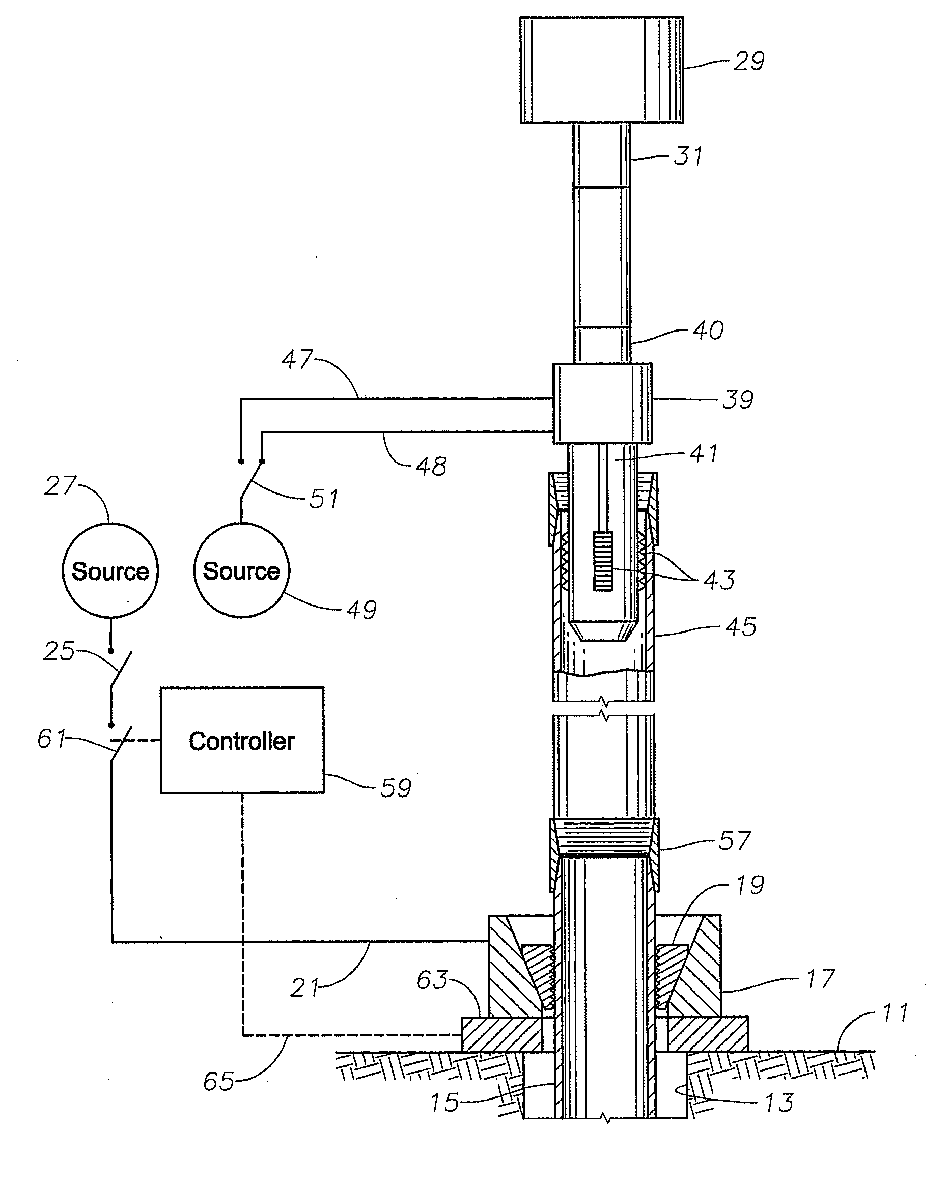
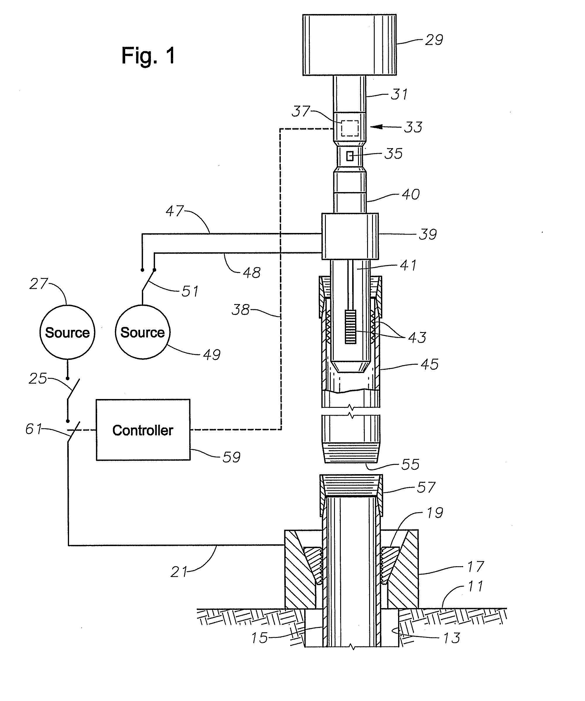
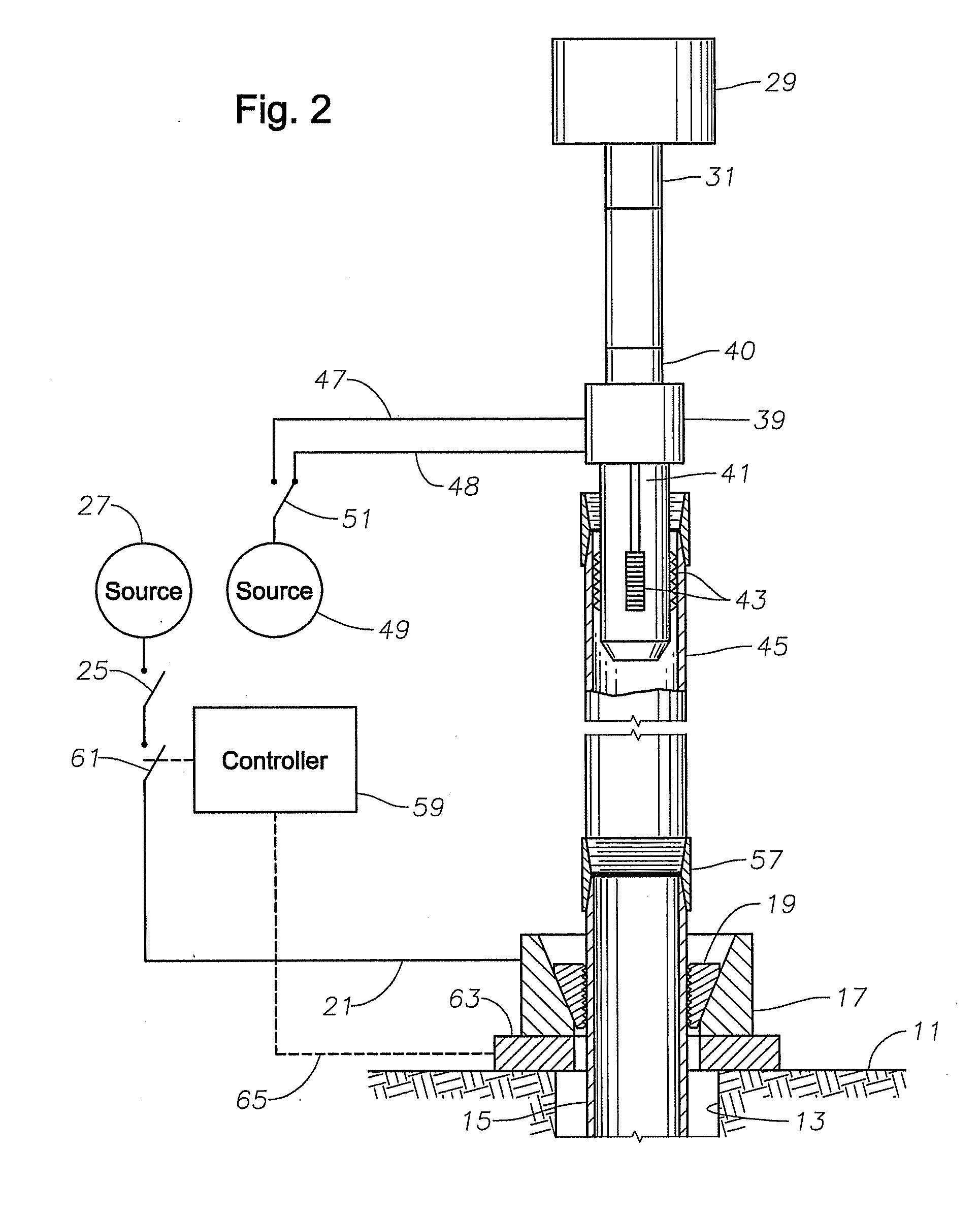
[0013]Referring to FIG. 1, a drilling rig has a rig floor 11 with an opening 13 aligned with a well (not shown). Opening 13 may be a rotary table. A casing string 15 is shown extending into the well through opening 13. Casing string 15 is made up of pipe intended to line the well bore and be cemented in place. Casing string 15 also may be employed to perform drilling of the well bore before it is cemented in place. Alternately, the well bore may have already been drilled by drill pipe and casing string 15 is being run into the well bore. Although the term “casing string” is employed, the pipe could either be what is conventionally referred to as casing or what is conventionally referred to as liner. The pipe for both casing and liner may be the same; however casing extends all from the bottom of the well bore all the way to the well head at the top of the well. A liner is also cemented in place but it typically extends only to a short distance above the lower end of a preceding stri...


PUM


Abstract

A method of running casing into a well utilizes a load sensor to avoid dropping the casing string accidentally. The rig has a spider at the rig floor that suspends a casing string in the well when in a gripping position. A casing lifting mechanism will place a new joint of casing on the casing string suspended in the spider. The new joint of casing is rotated to make up with the casing string. After makeup, the casing lifting mechanism lifts the new joint of casing and the casing string. The operator releases the spider to allow the casing string to be lowered further into the well. Before releasing the spider, a load sensor will send a signal indicating that the casing lifting mechanism is supporting a minimum amount of weight.

Description

FIELD OF THE INVENTION [0001]This invention relates in general to running casing into a well bore, and in particular a method of avoiding dropping the casing while it is being run.BACKGROUND OF THE INVENTION [0002]Most oil and gas wells are drilled by a drill string made up of drill pipe. At various depths and at the total depth, the operator will remove the drill pipe, then run in a string of casing. The casing lines the well bore and is cemented in place. In another technique, casing is employed as the drill string and when reaching a desired depth, it is cemented in place.[0003]When running casing into a well either for casing the well or for casing drilling the well, normally a powered spider is employed at the drill rig floor. The powered spider is a device that encircles the hole in the rig floor. It has segments or slips that will slide down to a gripping position gripping the casing string suspended in the well bore. Fluid power, typically hydraulic, is employed to move the ...

Claims


Application Information

Patent Timeline
Patent Type & Authority Applications(United States)
IPC IPC(8): E21B19/16
CPCE21B19/10E21B40/00E21B19/165E21B41/0021E21B19/16
Inventor SCHNEIDER, WARREN P.
Owner NABORS DRILLING TECH USA INC
Why Eureka
Try Eureka