
Aquarium Backlight

Inactive Publication Date: 2011-03-03
LEE SANG SOO
View PDF7 Cites 5 Cited by
  • Summary
  • Abstract
  • Description
  • Claims
  • Application Information

AI Technical Summary

Benefits of technology

[0008]The present system uses lighting distributed behind the back wall containing decorative scene to accomplish this task. Because the illumination source is located behind the wall of the enclosure (and not at the top), the thickness of the apparatus can be manipulated to allow for the use of a water filter, or other needed device, on the same wall. Moreover, the present invention is easy to install and cost-efficient, making it available to the everyday aquarium, terrarium, or similar enclosure hobbyist.
[0013]The present invention is very affordable and easy to implement. The illumination apparatus of the present invention may be made of inexpensive, durable, and easy to maintain materials.
[0016]One object of the present invention is to provide a cost effective, easy to install illumination apparatus to illuminate a wall of an aquarium, terrarium, or similar enclosure having a decorative scene on the wall.
[0017]It is a further object of the present invention to provide a pleasing aesthetic to an aquarium, terrarium, or similar enclosure by providing backlight to a decorative scene therein.
[0018]It is a further object of the present invention to provide an illumination apparatus that allows for the use of a filtration system (or similar apparatus used for the care of the enclosure) in conjunction with the illumination apparatus without conflict.

Problems solved by technology

One applied the decorative background, though semi-opaque in nature, may be difficult to view due to inadequate illumination from behind the wall.
Traditional overhead lighting provided by a light within the lid of the enclosure is insufficient.
Moreover, illumination provided by an ordinary lamp or daylight is not optimal due to availability and non-uniform distribution of illumination.
Previous attempts to address this issue describe an apparatus utilizing top-down illumination and reflective material, which do not achieve the desired effect of strong illumination (see U.S. application Ser. No. 11 / 953,299).
Moreover, a triangular-shaped apparatus using an illumination source at the top of the apparatus, and reflective material below, does not accommodate the needs of a water filter where the apparatus is used with an aquarium.
The large thickness of the light prevents the water filter from being able to be installed on the same wall.

Method used


Image

  • Aquarium Backlight
  • Aquarium Backlight
  • Aquarium Backlight

Examples


Embodiment Construction

[0025]The detailed explanation of the present invention is described below. The described preferred embodiments are presented for the purpose of illustration and description; they are not intended to limit the scope of the present invention. As will be apparent to one skilled in the art, modifications to described elements below may be made without deviating from the scope of the present invention.

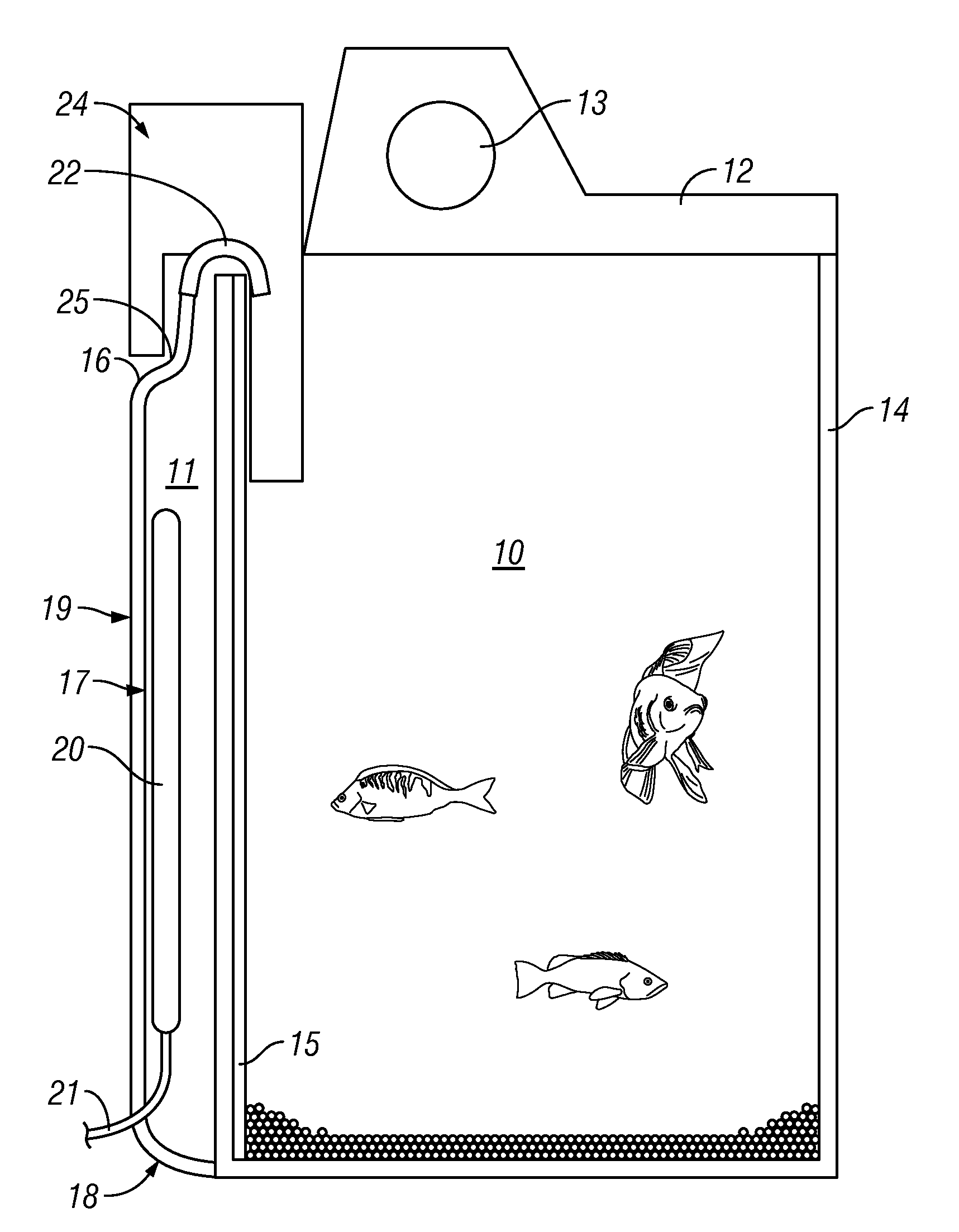
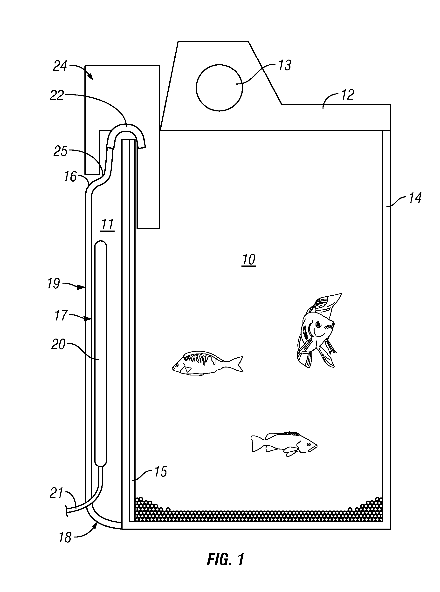
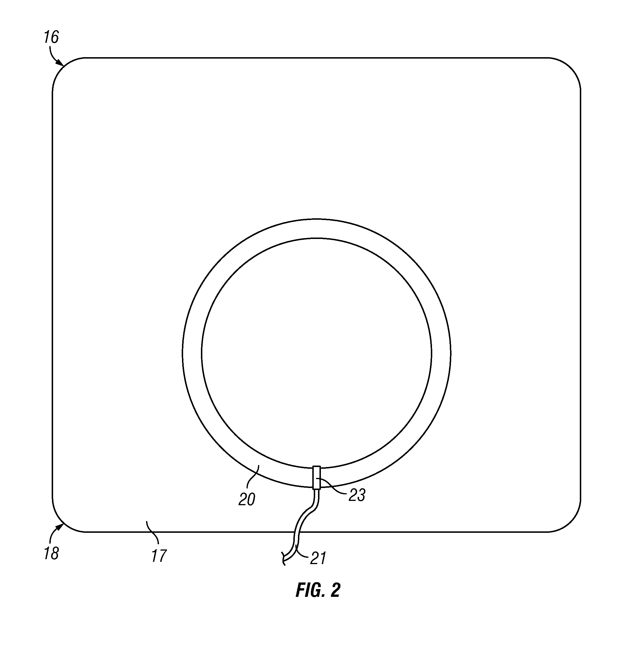
[0026]FIG. 1 shows a cross-sectional view of the illumination apparatus installed on an aquarium containing a water filter, according to one embodiment of the invention. Similarly, FIG. 3 shows the same view of the illumination apparatus, but without the water filter, where the filter is unnecessary as in embodiments where the apparatus is a terrarium, or other enclosure. The illumination apparatus can be fabricated from a variety of materials including, but not limited to, plastics, polymers, fiberglass, epoxies, resins, polycarbonates, molding compounds, glues, woods, glass, and metals. ...


PUM


Abstract

This invention is an illumination apparatus for an aquarium. In particular, the invention illuminates the back wall of the aquarium where the wall has a decorative panel of scenery. The illumination apparatus may be used in aquariums, terrariums, or similar enclosures. The illumination apparatus of the present invention allows for the use of filtration systems and other caretaking systems on the same wall as the illumination apparatus. The present invention uniformly illuminates the decorative panel and the aquarium, providing a pleasing effect.

Description

BACKGROUND[0001]1. Field of Invention[0002]This invention relates to an illumination apparatus for an aquarium. In particular, the invention illuminates the back wall of the aquarium where the wall has a decorative panel of scenery. The illumination apparatus may be used in aquariums, terrariums, or similar enclosures. The illumination apparatus of the present invention allows for the use of filtration systems and other caretaking systems on the same wall as the illumination apparatus. The present invention uniformly illuminates the decorative panel and the aquarium, providing a pleasing effect.[0003]2. Brief Description of the Prior Art[0004]Aquariums, terrariums, and other enclosures with transparent walls have been illuminated in a variety of ways. In addition to the traditional lighting provided from a housing that is placed on top of the aquarium, attachments to the walls of the aquarium that provide illumination have been described. Illumination provides a pleasing appearance ...

Claims


Application Information

Patent Timeline
IPC IPC(8): A01K63/06A01K63/00
CPCA01K63/06
Inventor LEE, SANG SOO
Owner LEE SANG SOO
Learn More