inertised destemming machine

a destemming machine and inert gas technology, applied in the field of destemming machines, can solve problems such as the detriment of the quality of wine, and achieve the effect of reducing the leakage of inert gas

Inactive Publication Date: 2011-03-03
FIRMA DIERMME SNC
View PDF5 Cites 27 Cited by
  • Summary
  • Abstract
  • Description
  • Claims
  • Application Information

AI Technical Summary

Benefits of technology

[0010]In a preferred embodiment of the invention, a valve is associated to the inlet mouth, which valve has the function of isolating the internal volume of the machine from the surrounding environment such as to keep to a minimum both the leakage of inertising gas towards the external environment and the inlet of air internally of the machine during the loading of the product. The valve is preferably a rotary valve comprising a cylindrical body provided with an inlet opening and an outlet opening for the product and internally of which an obturator organ is housed, rotating about the ax

Problems solved by technology

Destemming machines of the prior art however operate in normal environments and this means that the grapes subjected to the destemming operation,

Method used


Image

  •  inertised destemming machine
  •  inertised destemming machine
  •  inertised destemming machine

Examples


Embodiment Construction

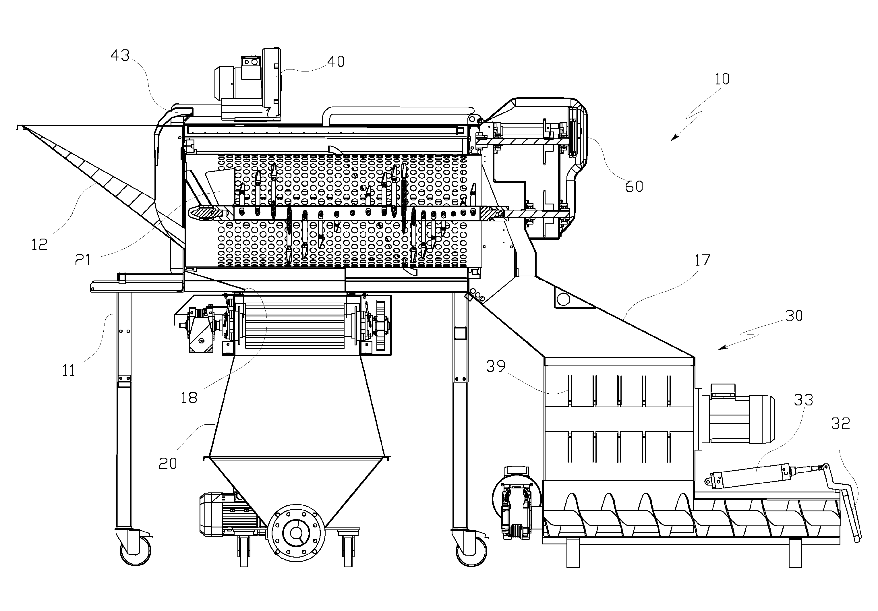
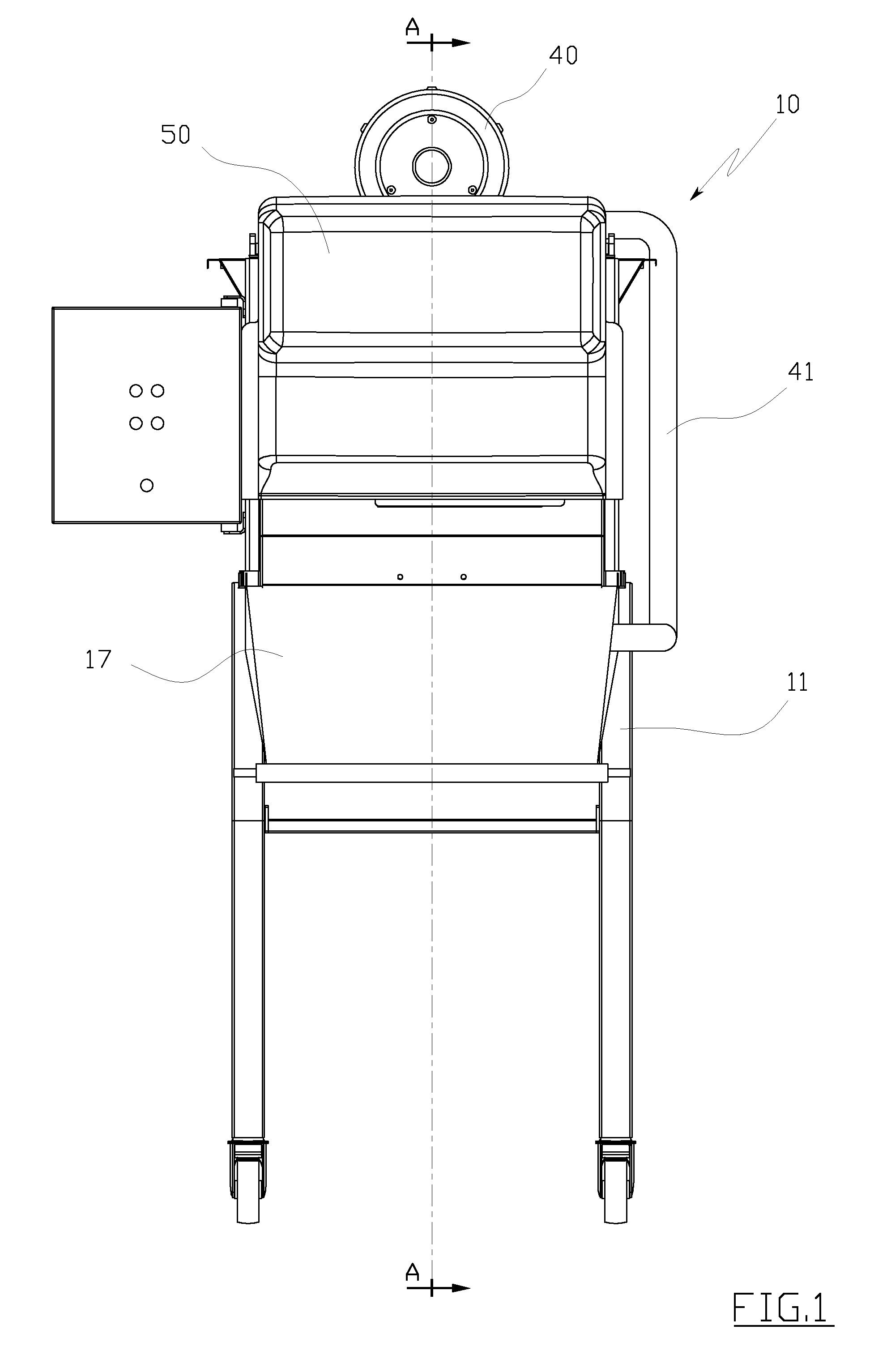
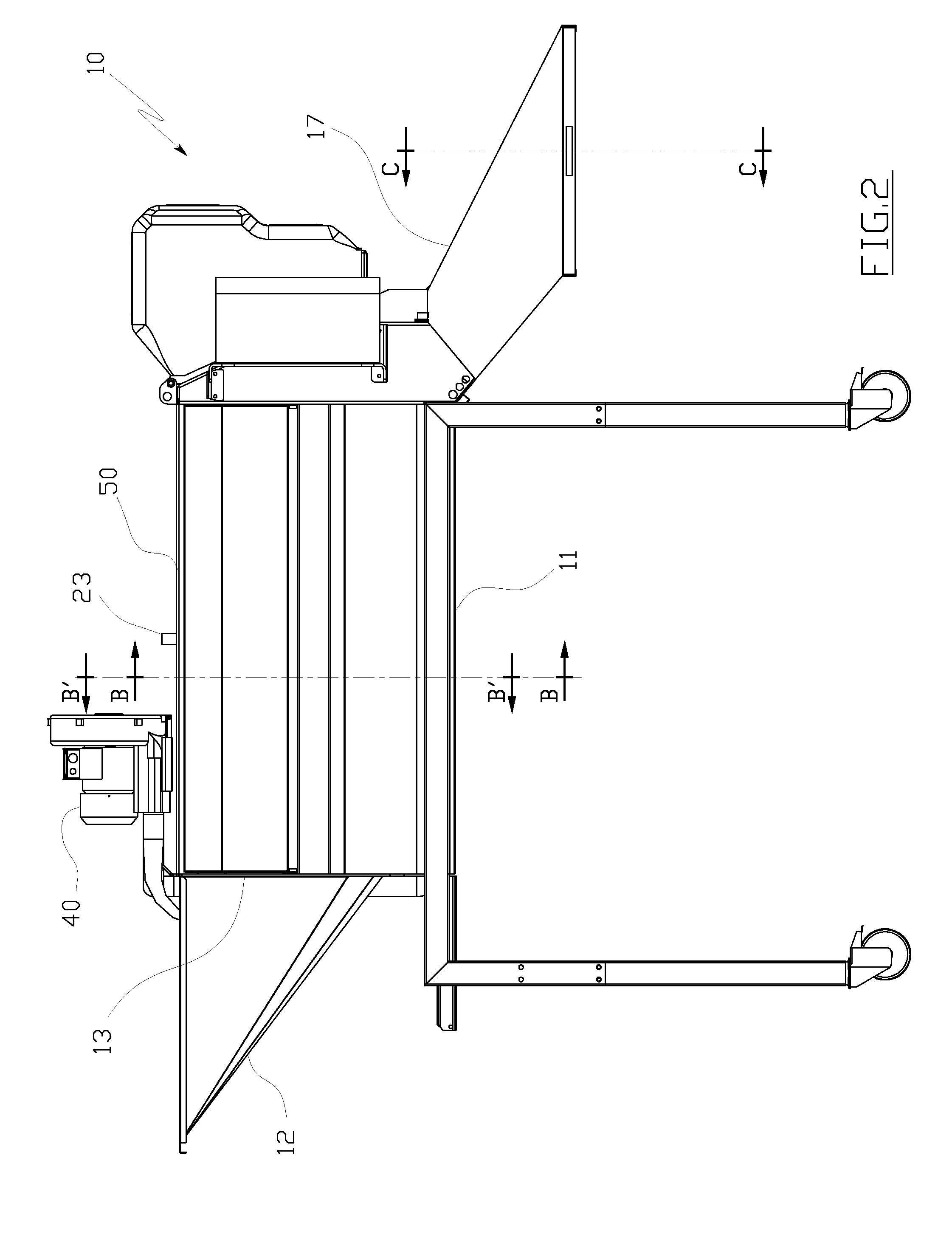
[0024]The figures of the drawings illustrate a destemming machine, denoted in its entirety by reference number 10, comprising a frame 11 to which a hopper 12 is associated for loading material to be destemmed, in particular bunches of grapes, into an inlet mouth 13 of the machine.

[0025]A machine body 50 is supported on the frame 11, which machine body 50 contains a rotary perforated drum 14 internally of which a shaft 15 rotates, the shaft 15 being equipped with a series of blades 16 terminating with ends 16′ designed to beat the bunches of grapes in order to detach the grapes from the stems and stalks, the blades 16 being organised in a helical configuration which pushes the working material, and in particular the stalks and stems, towards an outlet mouth for the stalks and stems (towards the right in FIG. 6).

[0026]Upstream of the blade group 16, and at the inlet mouth 13 for the bunches of grapes into the machine, a group of two or more blades 21 is located for conveying the grape...


PUM


Abstract

A destemming machine (10) comprising a frame (11) which houses a machine body (5) to which a hopper (12) is associated to enable inlet of material to be destemmed into an inlet mouth (13) of the machine body (50), at least a rotary perforated drum (14) contained internally of the machine body (50) internally of which a shaft rotates (15), which shaft is provided with blades (16) arranged in a helical fashion in order to perform a destemming action, the machine (10) comprising at least an outlet mouth (18) of the destemmed grapes and an outlet mouth (17) of the stems. The destemming machine (10) includes means for injecting and circulating an inertising gas (40) internally thereof.

Description

TECHNICAL FIELD [0001]The invention relates to a destemming machine.[0002]As is known, destemming machines have the function of separating the grapes from the woody part of the bunches, i.e. from the stems.BACKGROUND ART [0003]Destemming machines are generally constituted by a rotary perforated drum internally of which a shaft bearing helically-arranged blades rotates, the shaft and blades functioning as beaters for separating the stalks and stems from the grapes, the whole complex of elements being mounted on a metal frame, and the rotating drum and shaft being generally activated by a gear reducer group or other similar means for rotating.[0004]The bunches of grapes are introduced into the machine from a hopper and are beaten by the beater shaft against the walls of the perforated drum, the perforations being sufficiently large to easily enable passage of the grapes while the stems and stalks are retained internally of the drum and are then transported by the action of the beater ...

Claims


Application Information

Patent Timeline
IPC IPC(8): A23N15/02
CPCA23N15/025A23N15/02A01G17/026
Inventor MELANDRI, FILIPPOMELANDRI, GIUSEPPE
Owner FIRMA DIERMME SNC
Why Eureka
Try Eureka