
Zoom lens and image pickup apparatus

Inactive Publication Date: 2011-02-24
FUJIFILM CORP
View PDF7 Cites 2 Cited by
  • Summary
  • Abstract
  • Description
  • Claims
  • Application Information

AI Technical Summary

Benefits of technology

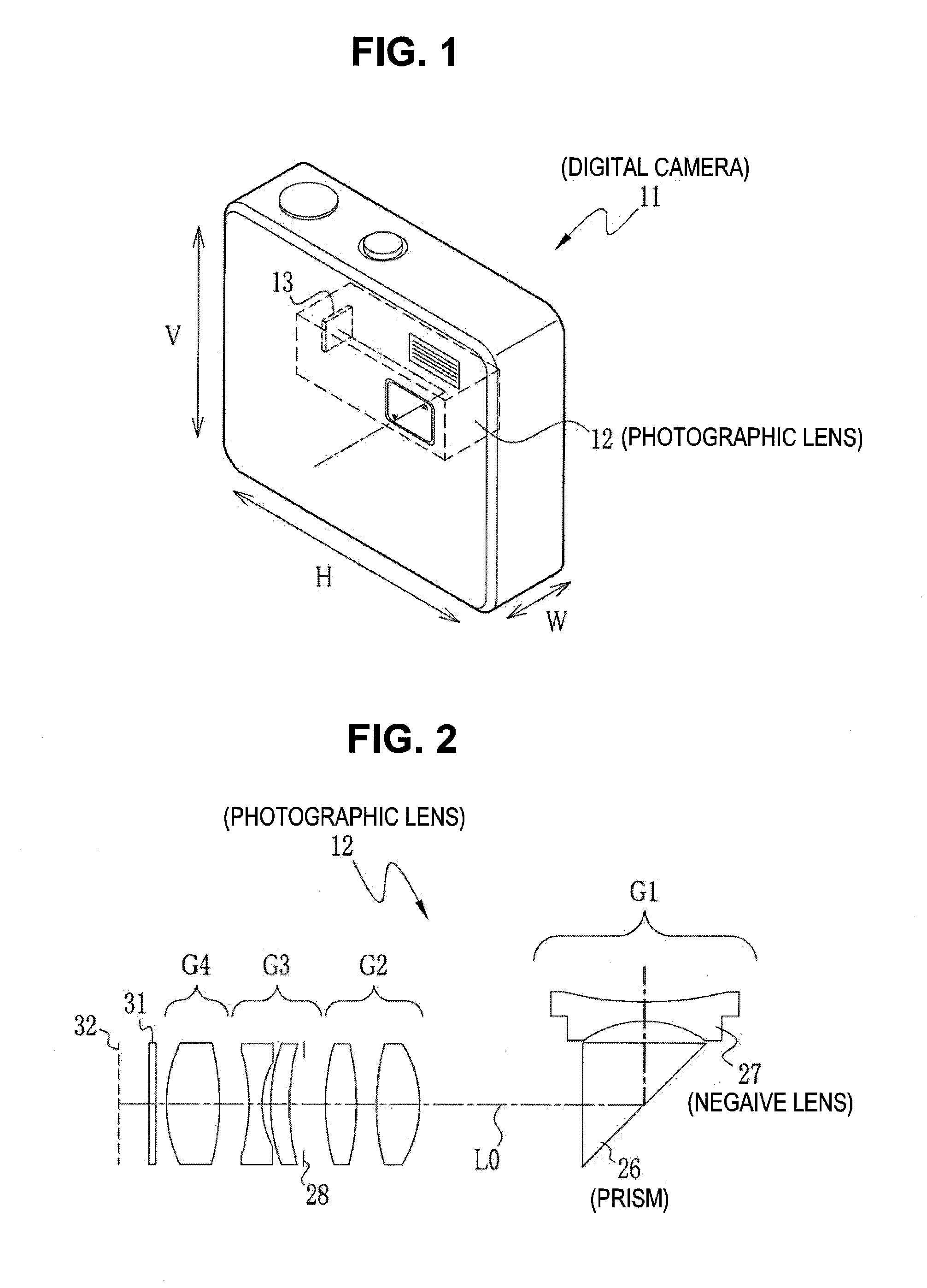
[0021]As a result, according to the embodiments of the invention, in photographic lenses that deflect the optical path through a prism, it is possible to provide a photographic lens which is configured so as to have a short length as a whole by preventing the lenses disposed in the front and the rear of the prism from physically interfering with each other and in which the optical axes of the prism and the lenses disposed in the front and the rear of the prism are precisely aligned with each other at the time of the assembly. Further, by employing the photographic lens, it is possible to provide an image pickup apparatus reduced in size and thickness.

Problems solved by technology

However, when the non-rotationally symmetric lens of which the outer peripheral portion has the notch formed thereon is used in the photographic lens as described above, it may be difficult to obtain a desired optical performance.
For example, the front and rear surface of the lens may be eccentric, or manufacturing errors such as assembly errors and processing errors of members which support lenses may occur.
However, when the non-rotationally symmetric lens is used in the photographic lens, arrangement of lenses is restricted by the shape and the directivity of the notch.
For this reason, it may be difficult to perform fine adjustment using rotation of rotationally symmetric lenses about the optical axis as the center, and thus it may also be difficult to obtain desirable optical performance.
Hence, it is difficult to perform the above-mentioned alignment of the optical axes using the rotation of the lenses, and it is difficult to obtain desirable optical performance.

Method used


Image

  • Zoom lens and image pickup apparatus
  • Zoom lens and image pickup apparatus
  • Zoom lens and image pickup apparatus

Examples


example 1

[0058]In Example 1, a notch is formed on the prism side of the negative lens, which is disposed in the front of the prism, along the outer periphery thereof, and the movable lens is disposed just behind the prism. As shown in FIGS. 7A and 7B, the photographic lens 110 according to Example 1 includes four lens groups of the first to fourth lens groups G1 to G4. FIG. 7A shows arrangement of the lens groups G1 to G4 at the wide-angle end, and FIG. 7B shows arrangement of the lens groups G1 to G4 at the telephoto end. Further, Table 1 shows lens data of the photographic lens 110 according to Example 1, Table 2 shows zoom data, and Table 3 shows aspheric surface coefficients.

TABLE 1EXAMPLE 1 • BASIC LENS DATARiDiNdνdSi(RADIUS(ON-AXIS(REFRAC-(ABBE(SURFACEOF CUR-SURFACETIVENUM-NUMBER)VATURE)SPACING)INDEX)BER)*1−3.86680.221.5153763.3*21.21000.253∞1.431.7859044.24∞D4(VARIABLE)*51.29170.501.4713676.6*6−2.73590.2372.97910.361.4970081.58−2.4583D8(VARIABLE)9 (APERTURE∞0.17STOP)*10−2.71530.221.62...

example 2

[0064]Example 2 is preferable in a case where a notch is formed on the prism side of the negative lens, which is disposed in the front of the prism, in a circular shape along the outer periphery thereof, and the stationary lens is disposed just behind the prism. As shown in FIGS. 9A and 9B, the photographic lens 120 according to Example 2 includes four lens groups of the first to fourth lens groups G1 to G4. FIG. 9A shows arrangement of the lens groups G1 to G4 at the wide-angle end, and FIG. 9B shows arrangement of the lens groups G1 to G4 at the telephoto end. Further, Table 4 shows lens data of the photographic lens 120 according to Example 2, Table 5 shows zoom data, and Table 6 shows aspheric surface coefficients.

TABLE 4EXAMPLE 2 • BASIC LENS DATARiDiNdνdSi(RADIUS(ON-AXIS(REFRAC-ABBE(SURFACEOF CUR-SURFACETIVENUM-NUMBER)VATURE)SPACING)INDEX)BER)1−9.78980.131.6134044.321.40160.213∞1.301.8830040.84∞0.03*54.23720.181.5095756.5*63.3805D6(VARIABLE)*70.84640.361.4713676 6*8−2.44530.12...

example 3

[0069]Example 3 is preferable in a case where a notch is formed on the prism side of the lens, which is disposed in the rear of the prism, in a circular shape along the outer periphery thereof, and the movable lens is disposed just behind the prism. As shown in FIGS. 10A and 10B, the photographic lens 130 according to Example 3 includes the first to fourth lens groups G1 to G4. FIG. 10A shows arrangement of the lens groups G1 to G4 at the wide-angle end, and FIG. 10B shows arrangement of the lens groups G1 to G4 at the telephoto end. Further, Table 7 shows lens data of the photographic lens 130 according to Example 3, Table 8 shows zoom data, and Table 9 shows aspheric surface coefficients.

TABLE 7EXAMPLE 3 • BASIC LENS DATARiDiNdνdSi(RADIUS(ON-AXIS(REFRAC-ABBE(SURFACEOF CUR-SURFACETIVENUM-NUMBER)VATURE)SPACING)INDEX)BER)*1−4.05570.221.5153763.3*21.25120.253∞1.431.7859044.24∞D4(VARIABLE)*51.36360.501.4713676.6*6−3.09230.1872.98320.361.4970081.58−2.2469D8(VARIABLE)9 (APERTURE∞0.22STOP...


PUM


Abstract

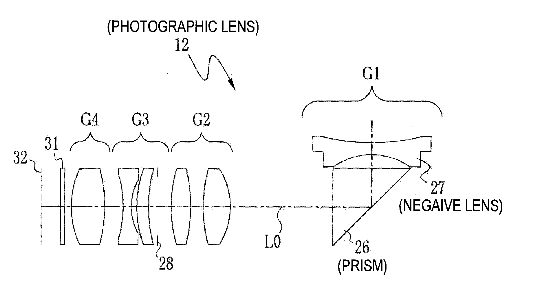
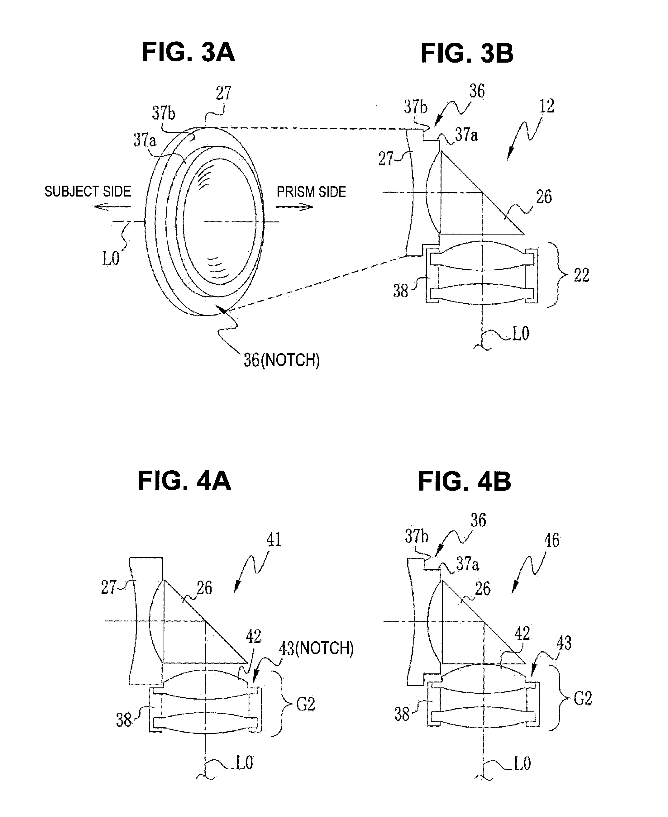
Provided is a photographic lens which prevents lenses disposed in the front and the rear of a prism from physically interfering with each other and in which the optical axes of the prism and the lenses disposed in the front and the rear of the prism are precisely aligned with each other. A photographic lens is a zoom lens that deflects the optical path of a prism and performs zooming by moving a second lens group and a third lens group disposed in the rear of the prism. A notch having a circular shape is formed on the prism side of a negative lens adjacent to the prism along the outer periphery of the lens. During zooming, when the second lens group is moved to the position close to the prism, the edge of the second lens group is fitted into the notch.

Description

CROSS-REFERENCE TO RELATED APPLICATIONS[0001]This application is based upon and claims the benefit of priority from the Japanese Patent Application No. 2009-191953 filed on Aug. 21, 2009; the entire contents of which are incorporated herein by reference.BACKGROUND OF THE INVENTION[0002]1. Field of the Invention[0003]The present invention relates to a zoom lens and an image pickup apparatus equipped with the zoom lens. Specifically, the invention relates to a zoom lens, which takes an image by deflecting light originated from a subject through a prism and performs zooming by moving the lens disposed in the rear of the prism and the like, and an image pickup apparatus using the same.[0004]2. Description of the Related Art[0005]Digital cameras for taking an image of a subject by using image pickup devices such as the CCD and the like have come into widespread use. Recently, digital cameras miniaturized to improve portability have spread, and particularly, thin-card-type digital cameras...

Claims


Application Information

Patent Timeline
IPC IPC(8): G02B15/14G03B17/00
CPCG02B15/177H04N5/2254G03B17/00G02B15/144511
Inventor KAWAMURA, DAIKISATO, KENICHI
Owner FUJIFILM CORP
Learn More