
Systems and methods for load compensation with primary-side sensing and regulation for flyback power converters

Active Publication Date: 2011-02-24
ON BRIGHT ELECTRONICS SHANGHAI
View PDF85 Cites 101 Cited by
  • Summary
  • Abstract
  • Description
  • Claims
  • Application Information

AI Technical Summary

Benefits of technology

[0031]Many benefits are achieved by way of the present invention over conventional techniques. Certain embodiments of the present invention provide a digitally-controlled nonlinear load compensation mechanism where the controller chip does not need an external pin for compensation. For example, the nonlinear load compensation mechanism resolves the issues of cross regulation between the consumption power of the controller chip and the output power of the power conversion system. In another example, the cross regulation often results in higher standby power loss and / or poor regulation at no load or light load conditions, but the nonlinear load compensation mechanism can achieve very low standby power loss and / or improve regulation of the output voltage of the power conversion system. Some embodiments of the present invention can reduce cost of the power conversion system. Certain embodiments of the present invention can provide external adjustment for the magnitude of load compensation.

Problems solved by technology

But the power conversion system 300 or 400 often cannot effectively offset the change in the output voltage as a function of the output current due to the resistance of the output cable.

Method used


Image

  • Systems and methods for load compensation with primary-side sensing and regulation for flyback power converters
  • Systems and methods for load compensation with primary-side sensing and regulation for flyback power converters
  • Systems and methods for load compensation with primary-side sensing and regulation for flyback power converters

Examples


Embodiment Construction

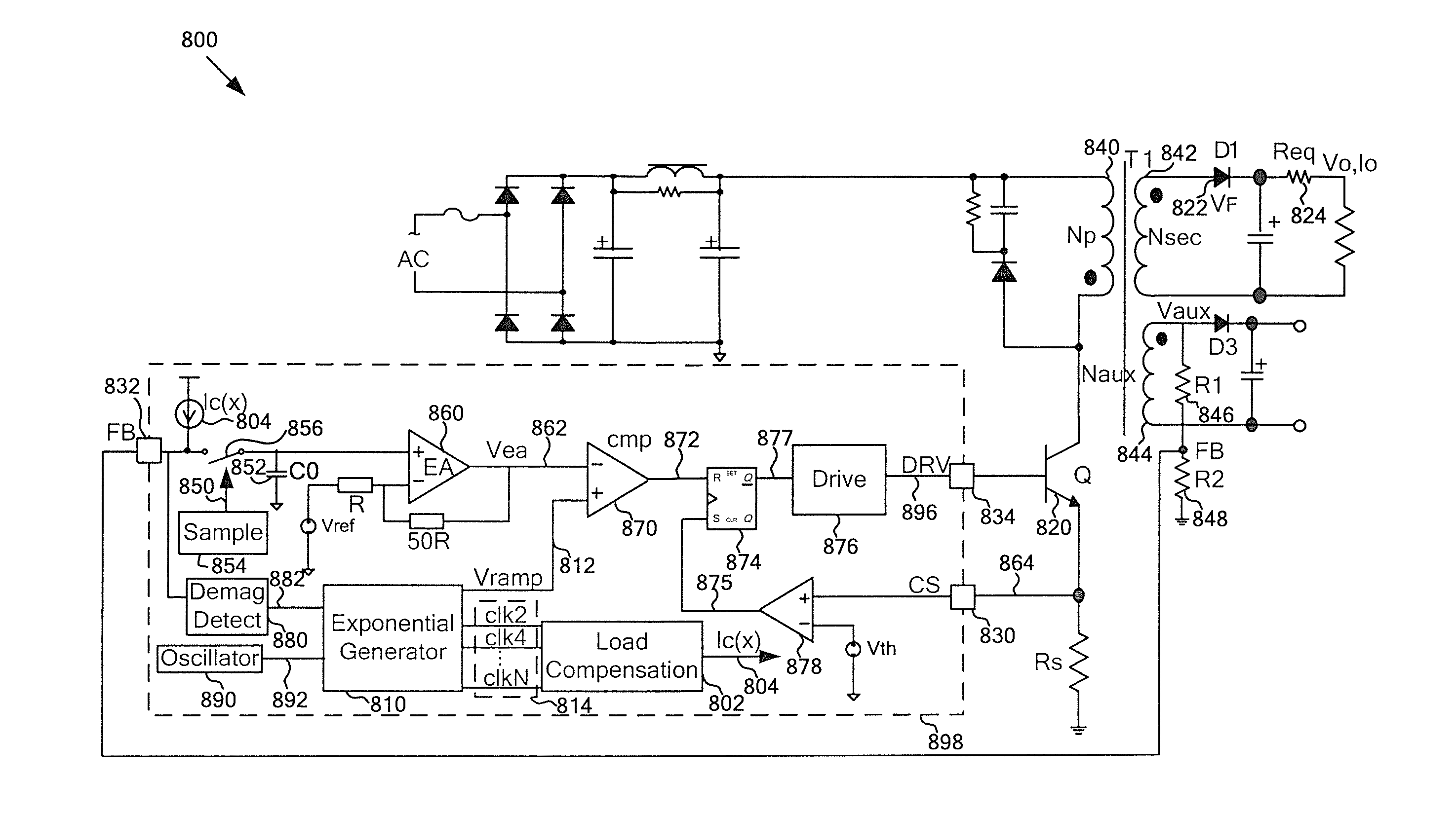
[0047]The present invention is directed to integrated circuits. More particularly, the invention provides systems and methods for load compensation with primary-side sensing and regulation. Merely by way of example, the invention has been applied to a flyback power converter. But it would be recognized that the invention has a much broader range of applicability.

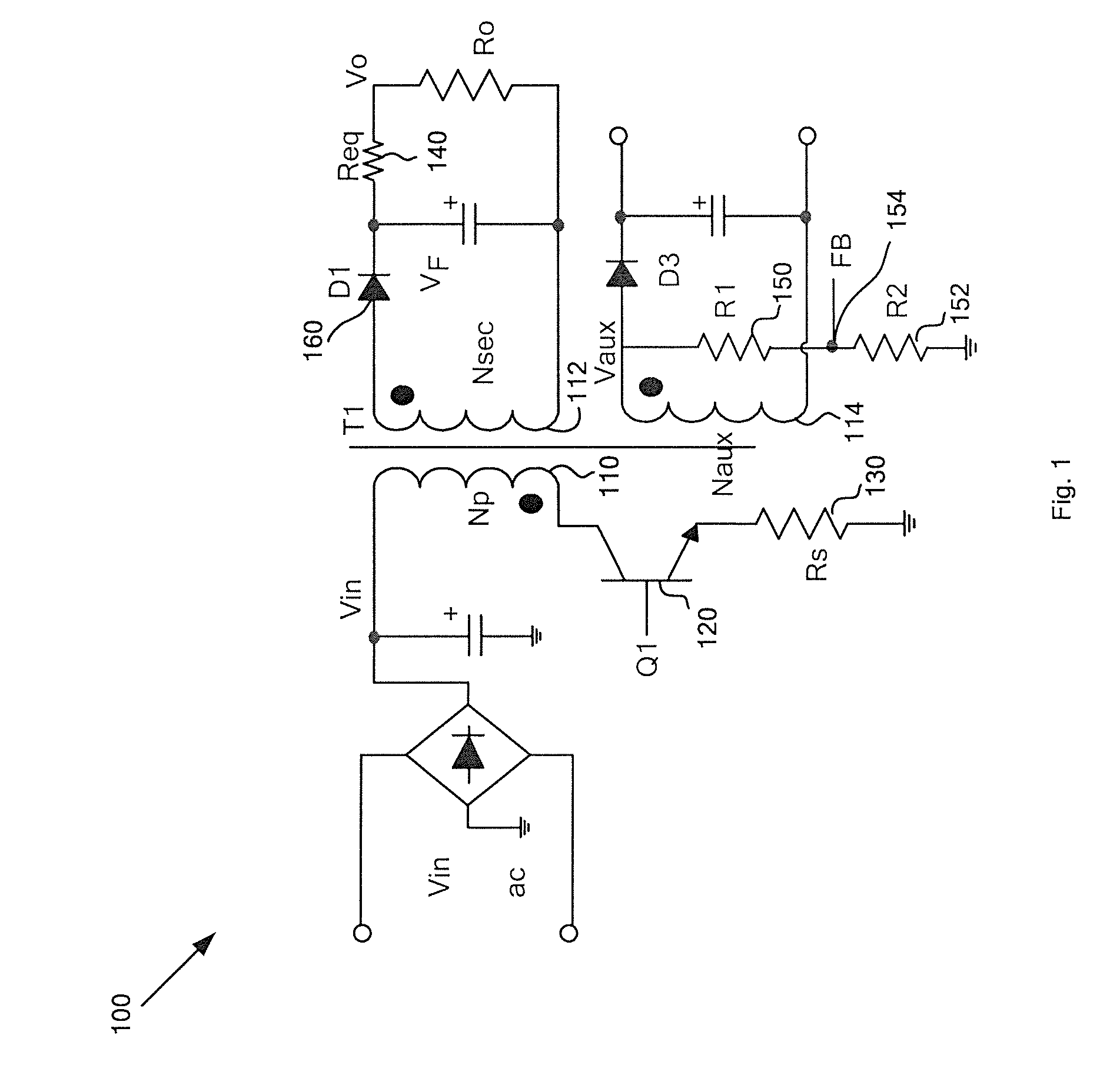
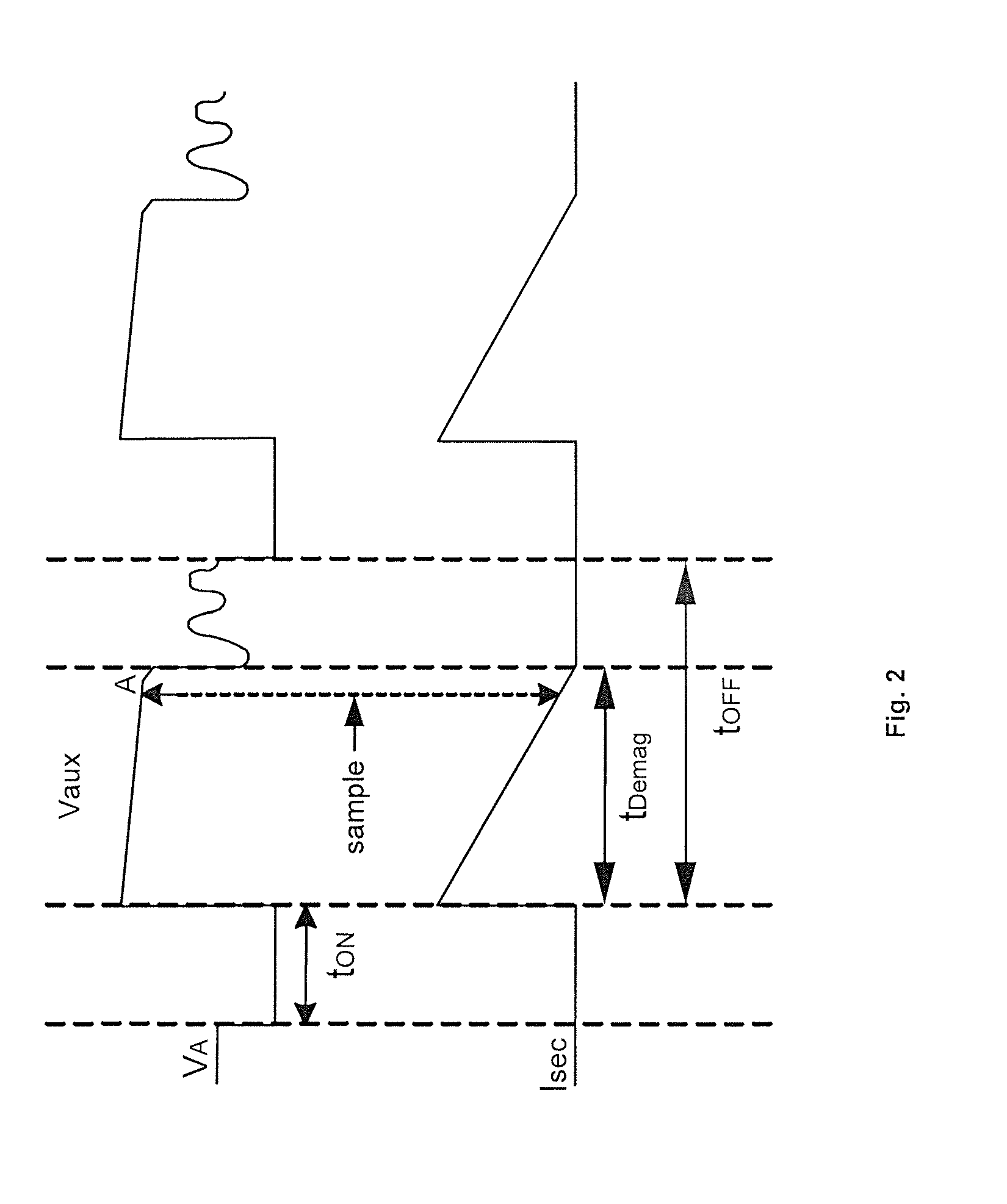
[0048]Referring to FIGS. 1 and 2, a compensation system is needed to offset the change in the output voltage as a function of the output current due to the resistance of the output cable. For example, in the discontinuous conduction mode (DCM), the energy transfer relationship for the flyback power conversion system 100 is

12×L×Ip2×Fs×η=Po=Vo×Io(Equation6)ThereforeIo=L×Ip2×Fs×η2×Vo(Equation7)

[0049]where L represents the conductance of the primary winding 110, and Ip, represents the peak current of the primary winding 110. Additionally, Fs represents the switching frequency of the power switch 120, and η represents the convers...


PUM


Abstract

System and method for regulating an output voltage of a power conversion system. The system includes a sampling component located on a chip configured to receive an input voltage through a terminal. The sampling component is configured to sample the input voltage and generate a sampled voltage. Additionally, the system includes an error amplifier configured to process information associated with the sampled voltage and a threshold voltage and generate a first output signal, and a first signal generator configured to generate a second output signal and one or more third output signals. Moreover, the system includes a comparator configured to receive the first output signal and the second output signal and generate a comparison signal, and a gate driver directly or indirectly coupled to the comparator and configured to generate a drive signal based on at least information associated with the comparison signal.

Description

1. CROSS-REFERENCES TO RELATED APPLICATIONS[0001]This application claims priority to U.S. Provisional Application No. 61 / 235,561, filed Aug. 20, 2009, commonly assigned, incorporated by reference herein for all purposes.2. BACKGROUND OF THE INVENTION[0002]The present invention is directed to integrated circuits. More particularly, the invention provides systems and methods for load compensation with primary-side sensing and regulation. Merely by way of example, the invention has been applied to a flyback power converter. But it would be recognized that the invention has a much broader range of applicability.[0003]Generally, a conventional power conversion system often uses a transformer to isolate the input voltage on the primary side and the output voltage on the secondary side. To regulate the output voltage, certain components, such as TL431 and an opto-coupler, can be used to transmit a feedback signal from the secondary side to a controller chip on the primary side. Alternative...

Claims


Application Information

Patent Timeline
IPC IPC(8): H02M3/335
CPCH02M3/33507Y02B70/16H02M2001/0032H02M2001/0019H02M1/0019H02M1/0032Y02B70/10
Inventor ZHANG, YUNCHAOFANG, LIEYI
Owner ON BRIGHT ELECTRONICS SHANGHAI
Learn More