LED driving circuit and driving controller for controlling the same

a technology of driving circuit and driving controller, which is applied in the direction of electric variable regulation, process and machine control, instruments, etc., can solve the problems of increasing power consumption, increasing unstable, and unable to identify the root cause of abnormalities, so as to increase the likelihood of damage, and increase the power consumption

Active Publication Date: 2011-02-24
GREEN SOLUTION TECH CO LTD
View PDF6 Cites 14 Cited by
  • Summary
  • Abstract
  • Description
  • Claims
  • Application Information

AI Technical Summary

Benefits of technology

[0007]In view of the drawback of the conventional technology may incur unnecessary power consumption, destabilize the whole circuitry, or even increase the likelihood of damaging it when operating abnormally, a driving circuit and a driving controller for the driving circuit in accordance with the present invention is disclosed. The driving controller for controlling the same according to present invention may remain in a protection mode when operating abnormally until the driving controller is restarted. Furthermore, the present invention may prevent misjudgment associated with abnormal operation.

Problems solved by technology

However, the root cause of abnormality may not be identified and eliminated by the stoppage of the transmission of the control signal Gate.
Therefore, the conventional approach may cause more power consumption, and more un-stable, and even increase the likelihood of damaging it.

Method used


Image

  • LED driving circuit and driving controller for controlling the same
  • LED driving circuit and driving controller for controlling the same
  • LED driving circuit and driving controller for controlling the same

Examples


Embodiment Construction

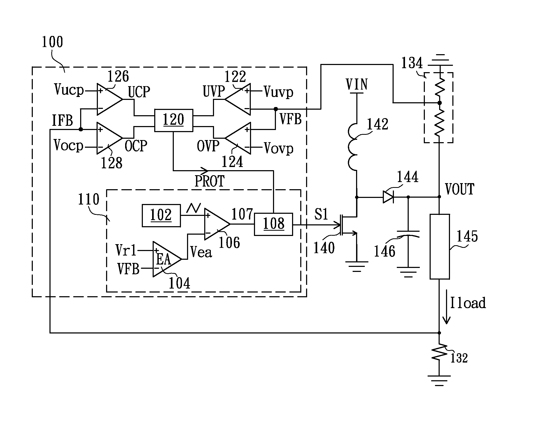
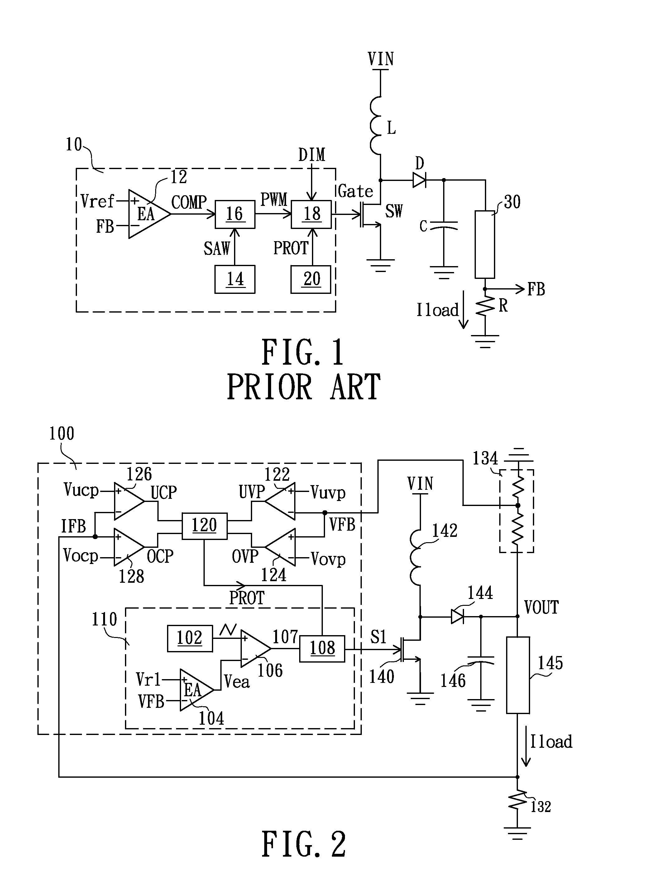
[0015]Please refer to FIG. 2 of a circuit diagram illustrating a driving circuit in accordance with one embodiment of the present invention. The driving circuit includes a controller 100 and a driving power supply for driving a load 145. The driving power supply includes a switch 140, an inductance 142, a diode 144, and an output capacitor 146. In one implementation, the driving power supply is a direct current to direct current (DC-DC) boost converting circuit for converting an inputted voltage VIN, coupled to the inductance 142, into an outputted voltage VOUT. The controller 100 receives a voltage feedback signal VFB generated from a voltage detection circuit 134. This voltage feedback signal VFB is indicative of a value of the outputted voltage VOUT. A control signal S1 is thus generated accordingly for controlling the switch 140 so as to stabilize the outputted voltage VOUT.

[0016]The controller 100 includes a feedback control unit 110 and a protection unit 120. The feedback cont...


PUM


Abstract

A driving controller for driving a load is disclosed. The driving circuit includes a driving power supply and the driving controller. The driving power supply provides a first power source to the load. The controller is coupled to a second power source to receive an electric power for operating. The controller controls the amount of the electric power to the load when operating in a first mode and stops the driving power supply from providing the electric power to the load when operating in a second mode. The controller operates exclusively in the first mode before the driving power supply provides the first power source to the load.

Description

BACKGROUND OF THE INVENTION[0001]1. Field of the Invention[0002]The present invention relates to a driving circuit and a light emitting diode (LED) driving controller, and more particularly to the LED driving circuit and the driving controller having a function of latch protection.[0003]2. Description of Related Art[0004]Reference is made to FIG. 1 showing a schematic diagram of the conventional driving circuit. The driving circuit has a converting circuit including an inductor L, a diode D, a transistor switch SW, and a capacitor C, and a controller 10. The driving circuit is used to drive a load 30, and a resistor R couples to this load 30 which generates a feedback signal FB according to the current flowing through the load 30. The controller 10 then generates a control signal Gate to control on or off state of the transistor switch SW according to the feedback signal FB. Accordingly, an electric power transferred from an inputted voltage VIN to an output end of the converting ci...

Claims


Application Information

Patent Timeline
Patent Type & Authority Applications(United States)
IPC IPC(8): H05B37/02H05B45/50
CPCH05B33/089H05B37/02H02H3/06H05B45/50H05B45/38H05B47/10H05B45/14
Inventor SHIU, SHIAN-SUNGLIU, JUANJUAN
Owner GREEN SOLUTION TECH CO LTD
Why Eureka
Try Eureka