Fan with dust-resistant coating

Inactive Publication Date: 2011-02-17
EBM PAPST ST GEORGEN & -
View PDF0 Cites 3 Cited by
  • Summary
  • Abstract
  • Description
  • Claims
  • Application Information

AI Technical Summary

Benefits of technology

[0004]It is therefore an object of the invention to provide an improved fan with dust-resistance characteristics. Preferably, this is accomplished by adding a preliminary step, of applying a solution incorporating nanoparticles, into the process of injection-molding plastic components of the fan. Through the binding of nanoparticles to the outer surface of the injection-molded fan wheel and similar components, one obtains a fan whose surface resists adherence of dust, thereby lengthening the time interval between necessary cleaning operations.
[0005]A fan whose outer surface contains nanoparticles can be simply cleaned by just spraying with water, since water beads up on such a treated surface and takes with it any dust which may have adhered to the fan wheel, for example. Thus, a simple cleaning procedure using an environmentally friendly medium is enabled. A further advantage is that painting or lacquering of the relevant components is no longer necessary.

Problems solved by technology

This dust tends to adhere to the fan blades and other components, which necessitates frequent cleaning of the soiled components.

Method used


Image

  • Fan with dust-resistant coating
  • Fan with dust-resistant coating
  • Fan with dust-resistant coating

Examples


Embodiment Construction

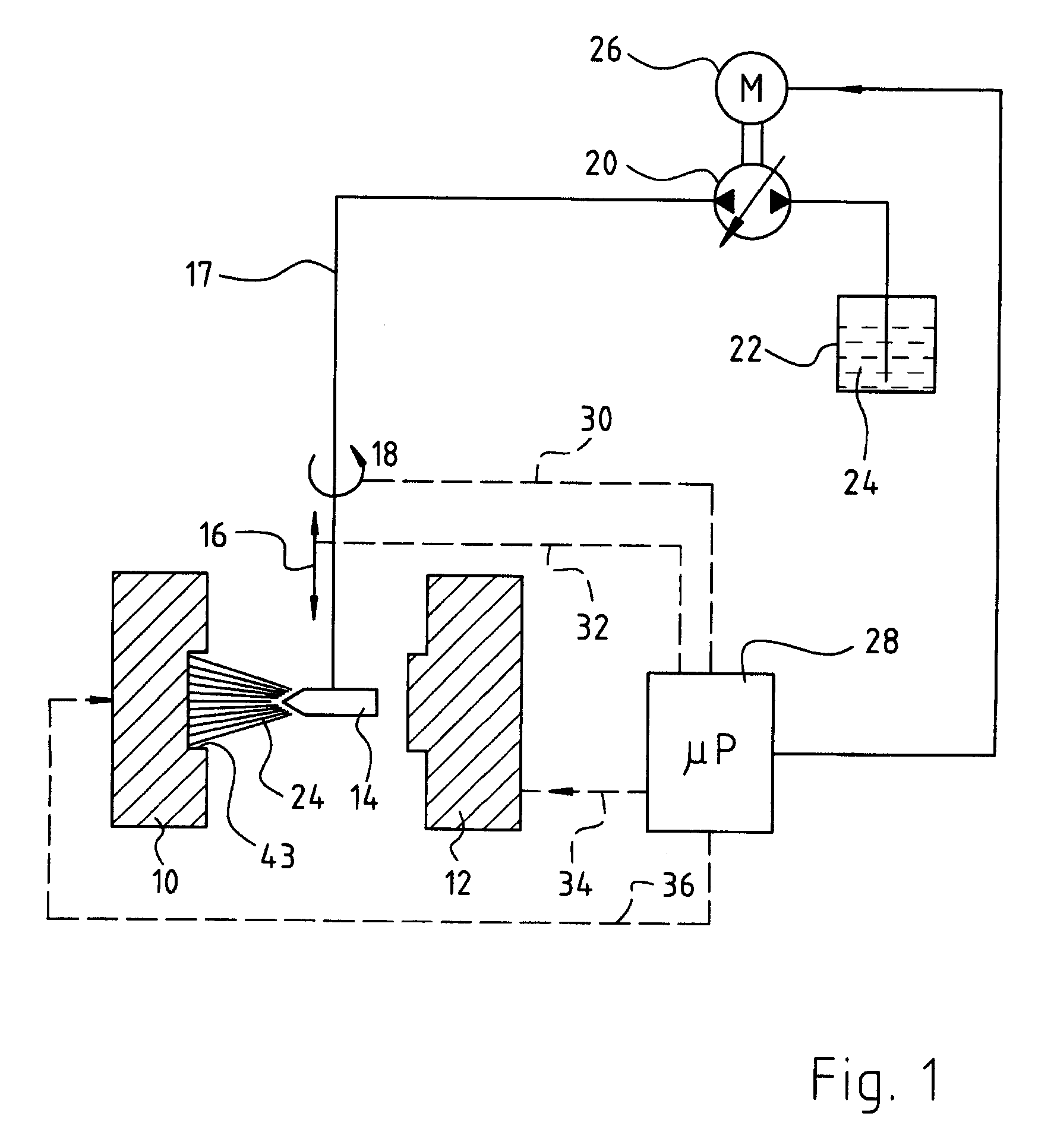
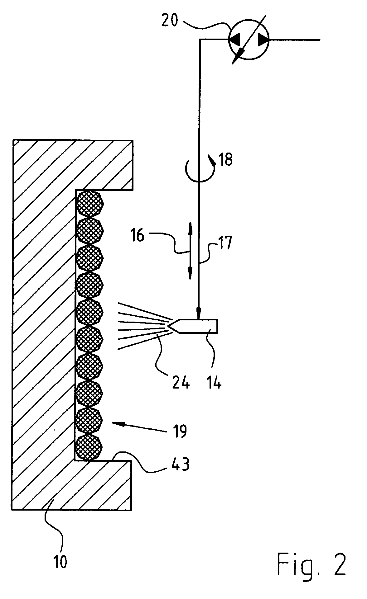
[0014]Between parts 10 and 12 of a mold, there is provided a nozzle head 14 which, as shown, is movable axially (as shown by arrow 16) and rotationally (as shown by arrow 18). Using a pump 20 and a supply line 17, the nozzle head 14 is coupled to a storage reservoir 22 containing a nanosolution 24. Suitable nanosolutions, for example nanoparticles in a propanol carrier, are known in the trade and therefore need not be described in detail here. For driving pump 20, a motor 26 is provided, controlled by a microprocessor 28. The latter also controls, via respective control signal lines 30 and 32, the rotation and axial movement of nozzle head 14. Microprocessor 28 also controls, via couplings 34, 36, the opening / closing movements of injection mold forms 10, 12.

Mode of Operation

[0015]Prior to making a fan component, the empty injection mold 10, 12 is opened, and the nozzle head 14 is moved, by an axial movement 16, into position between mold portions 10, 12. Motor 26 is actuated, so tha...


PUM

PropertyMeasurementUnit
Temperatureaaaaaaaaaa
Boiling pointaaaaaaaaaa

Abstract

A method of making a fan having one or more dust-resistant surfaces comprises the steps of: providing (S50) an open mold for injection-molding purposes, having a cavity (43) corresponding to the desired configuration of fan components to be formed; wetting (S52) the surface of the cavity (43) with a mixture (24) of nanoparticles (19) and a solvent carrier; evaporating (S54) said solvent carrier, thereby depositing said nanoparticles on the wall of the cavity (43); closing (S56) the injection mold (10, 12); injecting (S58) thermoplastic (42) into the cavity (43); permitting the thermoplastic to harden, thereby binding the nanoparticles into the surface of the thus-created component(s), and removing (S60) the completed component(s) from the mold, for subsequent assembly as part of a fan.

Description

CROSS-REFERENCE[0001]This application claims priority from my German application DE 10 2009 037 769.7 filed 17 Aug. 2009, the entire content of which is hereby incorporated by reference.FIELD OF THE INVENTION[0002]The present invention relates generally to a fan with a molded plastic component and, more particularly, to a method of making such a fan with improved dust-resistance characteristics.BACKGROUND[0003]Fans are often used in environments in which dust is present. This dust tends to adhere to the fan blades and other components, which necessitates frequent cleaning of the soiled components.SUMMARY OF THE INVENTION[0004]It is therefore an object of the invention to provide an improved fan with dust-resistance characteristics. Preferably, this is accomplished by adding a preliminary step, of applying a solution incorporating nanoparticles, into the process of injection-molding plastic components of the fan. Through the binding of nanoparticles to the outer surface of the inject...

Claims


Application Information

Patent Timeline
IPC IPC(8): F04D29/42B29C45/16F03B3/12
CPCB29C45/14778F04D29/281F04D29/023F05D2300/43F05D2300/603
Inventor DENNER, STEFAN
Owner EBM PAPST ST GEORGEN & -
Why Eureka
Try Eureka