
Integrated rotor pole pieces

a rotor and pole technology, applied in the direction of rotating magnets, magnetic circuit rotating parts, synchronous machines with stationary armatures, etc., can solve the problems of increasing the volume, weight and cost of the total drive, and low power factor, so as to facilitate the assembly of the rotor and increase the precision

Inactive Publication Date: 2011-02-17
HOGANAS AB
View PDF11 Cites 22 Cited by
  • Summary
  • Abstract
  • Description
  • Claims
  • Application Information

AI Technical Summary

Benefits of technology

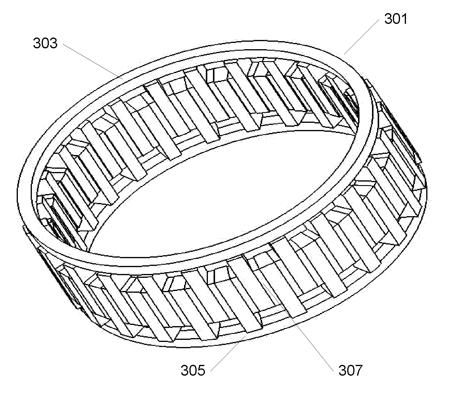
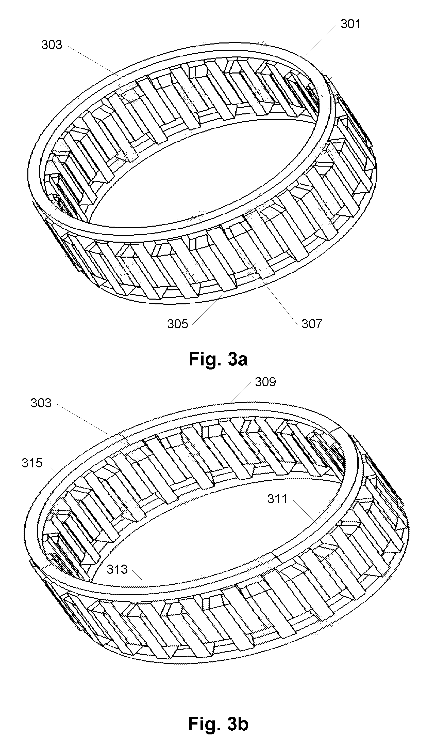
[0008]As the permanent magnets generate the rotor magnetic field, and since the permanent magnets are magnetically coupled directly to respective ones of the rotor pole sections, the integration bridge merely serves as a mechanical connection of the rotor pole sections with each other, so as to provide a stable arrangement of the rotor pole sections with well-defined distances between them, thereby facilitating fast and accurate arrangement of the permanent magnets in slots formed between the rotor pole sections. The integration bridge is not required and normally not even desired to carry magnetic flux, in particularly when the permanent magnets are the only magnetic source of the rotor structure, e.g. in a coilless rotor structure. Hence, the integration bridge may have a shape and a size large enough so as to provide sufficient mechanical strength to the pole piece structure to allow arrangement of the permanent magnets between the rotor pole sections. Furthermore, the integration bridge may have a shape and a size small enough so as to minimize any magnetic flux leakage.
[0024]Thereby the integrated pole sections are efficiently made in the same operation by use of a powder forming method where the forming is made in a single compaction tool set up.

Problems solved by technology

However, one of the drawbacks of the design is that they are typically relatively expensive to manufacture and that they experience a high leakage flux which causes a low power factor and a need for more magnet material.
The low power factor requires an up-sized power electronic circuit (or power supply when the machine is used synchronously) that also increases the volume, weight and cost of the total drive.
The assembly of these segments is further complicated by the opposing polarisation direction of the permanent magnet segments that will tend to repell the pole sections from each other during the assembly.
The integration bridge is not required and normally not even desired to carry magnetic flux, in particularly when the permanent magnets are the only magnetic source of the rotor structure, e.g. in a coilless rotor structure.

Method used


Image

  • Integrated rotor pole pieces
  • Integrated rotor pole pieces
  • Integrated rotor pole pieces

Examples


Embodiment Construction

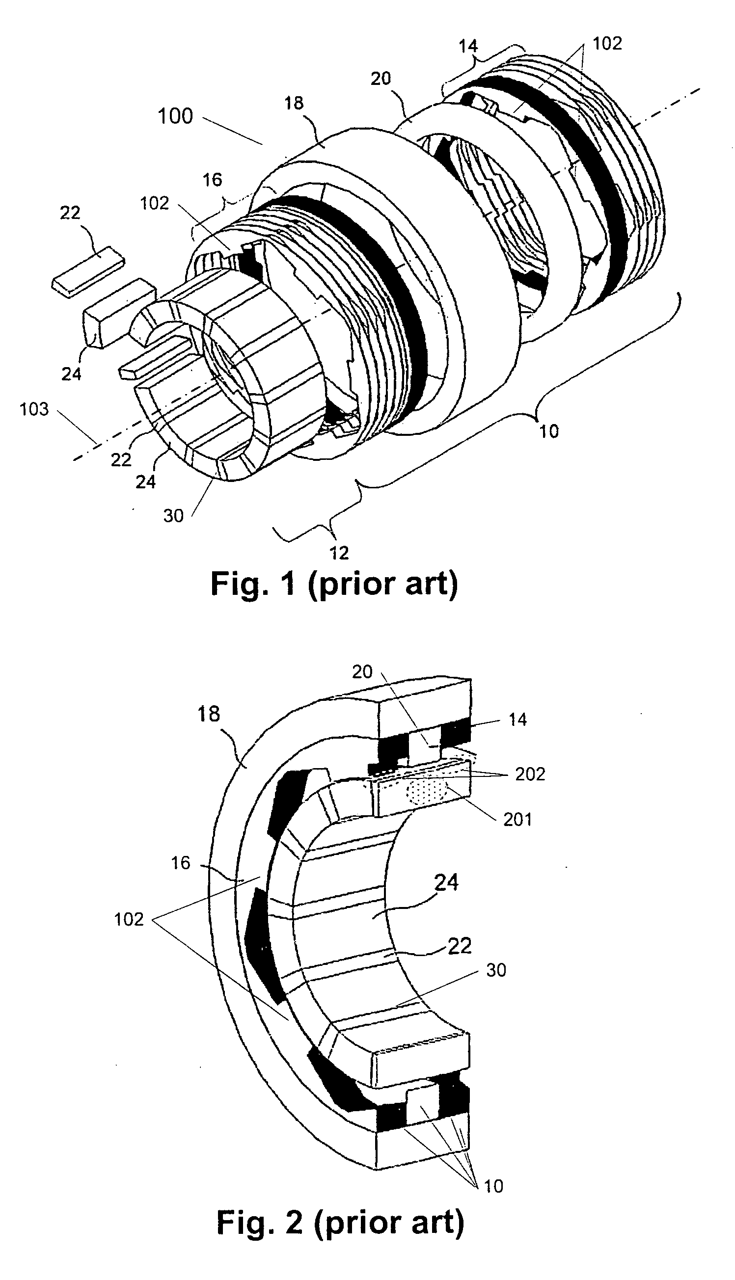
[0040]This invention is in the field of a modulated pole electric machine 100 of which one example is shown in FIG. 1 in a schematic, exploded, perspective view. The modulated pole electric machine stator 10 is basically characterised by the use of a central single winding 20 that will magnetically feed multiple teeth 102 formed by the soft magnetic core structure. The stator core is then formed around the winding 20 while for other common electrical machine structures the winding is formed around the individual tooth core section. Examples of the modulated pole machine topology are sometimes recognised as e.g. Claw-pole-, Crow-feet-, Lundell- or TFM-machines. More particularly the shown modulated pole electric machine 100 comprises two stator core sections 14, 16 each including a plurality of teeth 102 and being substantially circular, a coil 20 arranged between the first and second circular stator core sections, and a rotor 30 including a plurality of permanent magnets 22. Further...


PUM

PropertyMeasurementUnit
particle sizesaaaaaaaaaa
angleaaaaaaaaaa

Abstract

A pole piece structure is provided to be used as part of an active rotor structure for an electrical rotary machine, wherein the active rotor structure is circular comprising pole pieces and permanent magnets magnetised in the circumferential direction of the rotor structure, wherein the rotor pole piece structure is a single structure with at least two individually spaced pole pieces connected by an integration bridge. Further provided is a method of manufacturing a rotor pole piece structure and a rotor for an electrical machine with a rotor pole piece structure. The assembly of magnets to the pole pieces is significantly enhanced using these rotor pole piece structures as described.

Description

FIELD OF THE INVENTION[0001]The present invention relates to a rotor for an electrical rotary machine. The invention further relates to a method of manufacturing a rotor for an electrical rotary machine with a rotor pole piece structure. The assembly of magnets to the pole pieces is significantly enhanced using these rotor pole piece structures according to the present invention.BACKGROUND OF THE INVENTION[0002]During the years, electric machine designs evolved from modulated pole machines, claw pole machines, Lundell machines and transverse flux machines (TFM) have become more and more interesting. Electric machines using the principles of these machines were disclosed as early as about 1910 by Alexandersson and Fessenden. One of the most important reasons for the increasing interest is that the design enables a very high torque output in relation to, for instance, induction machines, switched reluctance machines and even permanent magnet brushless machines. Further, such machines ...

Claims


Application Information

Patent Timeline
Patent Type & Authority Applications(United States)
IPC IPC(8): H02K1/27H02K15/12H02K15/00
CPCH02K1/2773Y10T29/49009H02K21/145H02K1/274
Inventor NORD, GORANPENNANDER, LARS-OLOVJACK, ALAN G.
Owner HOGANAS AB
Learn More