
Flow sensor and production method thereof

a flow sensor and flow sensor technology, applied in the field of flow sensors, can solve the problems of impairing flow measurement quality, scarcely being able to achieve perfect sealing off the measuring channel, etc., and achieve the effect of low susceptibility to soiling, efficient and inexpensive production

Active Publication Date: 2011-02-17
BELIMO HOLDING AG
View PDF5 Cites 9 Cited by
  • Summary
  • Abstract
  • Description
  • Claims
  • Application Information

AI Technical Summary

Benefits of technology

The present invention provides a flow sensor and a method for its production that overcome the disadvantages of prior art flow sensors. The flow sensor has a sealing lip that surrounds and defines the flow channel, preventing deposition and accumulation of dirt particles, and allows for laminar flow through the flow channel. The base member is formed by two-component injection molding with a resilient material region that is joined to a more rigid material region, and the flow channel is separated from an outer channel. The method for production involves simply attaching a cover plate with the flow sensor element set in flush to the base member. These features make the flow sensor more resistant to soiling, prevent turbulence, and ensure smooth flow through the flow channel.

Problems solved by technology

It is however scarcely possible to achieve perfect sealing off of the measuring channel from the gap between the parts and at the same time completely to prevent penetration of adhesive into the measuring channel.
As a result of connections between the measuring channel and the gap between the housing parts and as a result of glue deposits in the measuring channel, dirt may accumulate, which may cause turbulent flow through the measuring channel and thus impair flow measurement quality.

Method used


Image

  • Flow sensor and production method thereof
  • Flow sensor and production method thereof
  • Flow sensor and production method thereof

Examples


Embodiment Construction

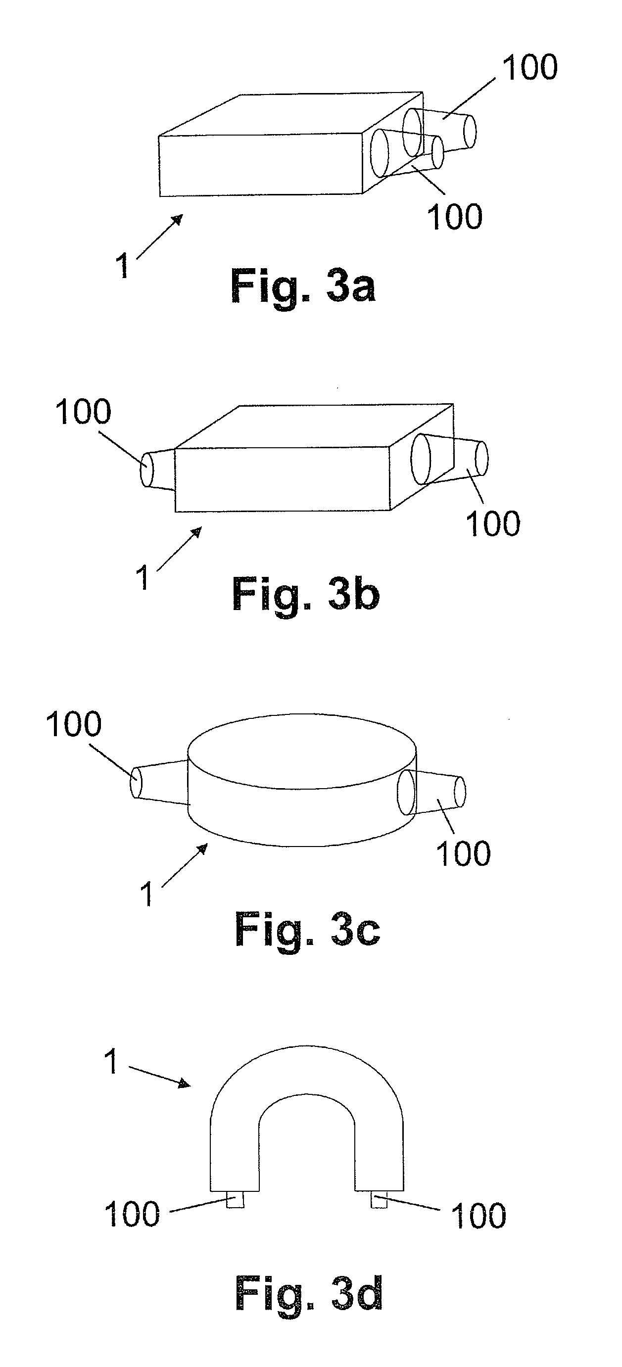
[0033]In FIGS. 1, 3a, 3b, 3c and 3d reference numeral 1 designates a flow sensor for measuring the flow of fluids, preferably of air or other gases. As is shown schematically in FIG. 1, the flow sensor 1 comprises a cover plate 12 and a base member 1′, which is also represented in various variant embodiments in FIGS. 2, 5, 7a and 7b. The cover plate 12 is mounted on the base member 1′ and attached to the base member 1′, for example by means of rivets 103, screws, adhesive or by welding. The cover plate 12 is for example a flat electronic epoxy printed circuit board.

[0034]The base member 1′ comprises a nonresilient region 10 and a resilient region 11 joined thereto. The resilient region 11 is arranged lying on the nonresilient region 10. The nonresilient, or at least substantially less resilient, harder region 10 compared with resilient region 11 consists for example of a plastics such as nylon polyamide. The resilient (softer) region 11 consists for example of a thermoplastic materi...


PUM

PropertyMeasurementUnit
internal diameteraaaaaaaaaa
widthaaaaaaaaaa
depthaaaaaaaaaa

Abstract

In a flow sensor (1) comprising a flow channel (14) embedded in a base body (1′), a flow sensor element (13) adjacent to the flow channel (14) and a cover plate (12) covering the flow channel (14) and arranged on the base body (1′), the flow channel (14) is formed by an elastic sealing lip which delimits said channel (14), running on and around an upper side of the base body (1′) lying opposite the cover plate (12) and is pressed against the cover plate (12) such that a seal is formed. The design of the flow channel (14) by means of the sealing lip (5) allows the flow channel (14) to be sealed off from possible gaps between the base body (1′) and the cover plate (12) and in relation to the cover plate (12), such that a flow channel with a level channel bed (14) is formed by the sealing lip (15) and the cover plate (12) which channel bed has smooth peripheral areas and a uniform cross-section, and which if possible avoids the depositing and collection of dirt particles and thus prevents undesirable turbulence in the flow channel (14) and guarantees a laminar current through the flow channel (14).

Description

FIELD OF THE INVENTION[0001]The present invention relates to a flow sensor and to a method for the production of the flow sensor, in particular a flow sensor for measuring the flow of fluids, in particular for measuring the flow of air and other gases. The present invention relates in particular to a flow sensor, and to a method for the production of the flow sensor, which comprises a base member with a flow channel, a flow sensor element adjoining the flow channel, and a cover plate arranged on the base member and covering the flow channel.BACKGROUND OF THE INVENTION[0002]EP 1 182 432 describes a flow sensor consisting of two housing parts for measuring the flow of fluids, which flow sensor comprises a semiconductor chip with sensor arrangement arranged between the housing parts. The semiconductor chip is located at a measuring channel configured as a groove in one of the housing parts. A sealing ring is additionally arranged between the housing parts. A strip conductor foil is gui...

Claims


Application Information

Patent Timeline
Patent Type & Authority Applications(United States)
IPC IPC(8): G01F15/14B23P11/00
CPCB01L3/502707Y10T29/49826G01F15/18G01F1/6845
Inventor HOLOCH, PHILIPMEGNET, KARINSTAHELI, CURDIN
Owner BELIMO HOLDING AG
Learn More