Method and device for regenerating a particle filter having an exhaust gas probe situated in the exhaust gas duct downstream thereof

a technology of particle filter and exhaust gas duct, which is applied in the direction of electric control, instruments, specific gravity measurement, etc., can solve the problems of affecting the performance of the engine, the negative effect of engine performance and fuel consumption, and the inability to freely select the mixture composition of the internal combustion engin

Inactive Publication Date: 2011-02-17
ROBERT BOSCH GMBH
View PDF6 Cites 11 Cited by
  • Summary
  • Abstract
  • Description
  • Claims
  • Application Information

AI Technical Summary

Benefits of technology

[0024]A simple evaluation of the signals of the lambda probes can be achieved as a result of a second program routine being provided in the control unit for the mixture oscillation resulting from a periodic change in the fuel mixture supplied to the internal combustion engine during the regeneration phase. A periodic change of lambda, preferably about a value of lambda=1, is brought about at the first lambda probe upstream of the particle filter by the mixture oscillation. During the lean periods of the mixture oscillation, said first lambda probe indicates a lambda>1. As a result of the consumption of the oxygen, the second lambda probe indicates a lower lambda value in comparison to the first lambda probe. The course of the regeneration of said particle filter can therefore be suggested from the signal flow of said second lambda probe in comparison with the signal of said first lambda probe across consecutive lean periods.

Problems solved by technology

Said particle filter clogs with time from the masses of soot deposited in the filter substrate.
This clogging becomes apparent by an increase in the exhaust gas back pressure, which has a negative effect on the engine performance and the fuel consumption.
Because an excess of oxygen must be present in the exhaust gas for a burning off of the particles to take place, the mixture composition of the internal combustion engine can not be freely selected in this phase according to the requirements of the driving operation.

Method used


Image

  • Method and device for regenerating a particle filter having an exhaust gas probe situated in the exhaust gas duct downstream thereof
  • Method and device for regenerating a particle filter having an exhaust gas probe situated in the exhaust gas duct downstream thereof
  • Method and device for regenerating a particle filter having an exhaust gas probe situated in the exhaust gas duct downstream thereof

Examples


Embodiment Construction

mplary embodiment depicted in the figures. The following are shown:

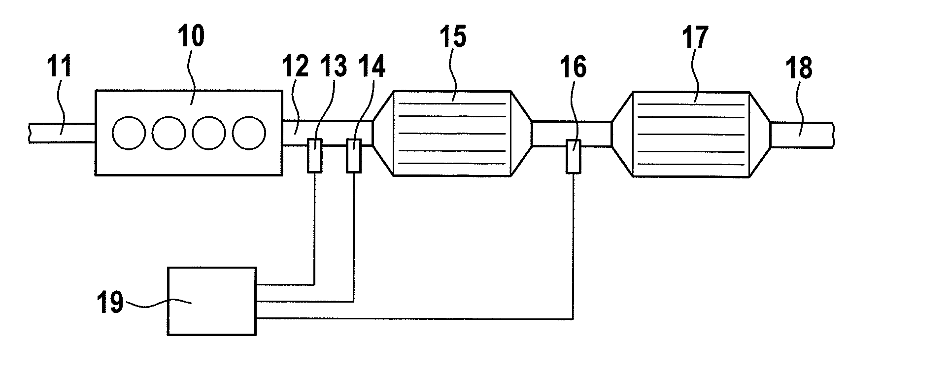
[0027]FIG. 1 is an internal combustion engine having a particle filter disposed in its exhaust gas duct and a three-way catalytic converter disposed downstream thereof,

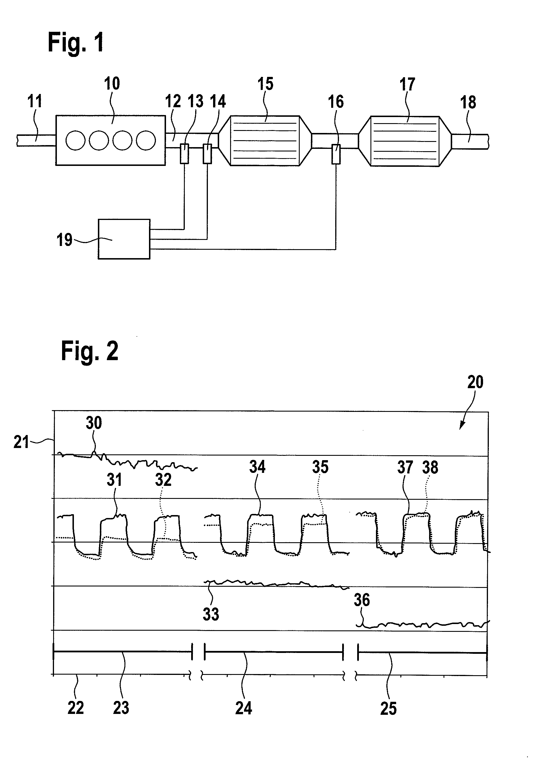
[0028]FIG. 2 is a signal flows during a regeneration of the particle filter when using wideband lambda probes in the exhaust gas duct,

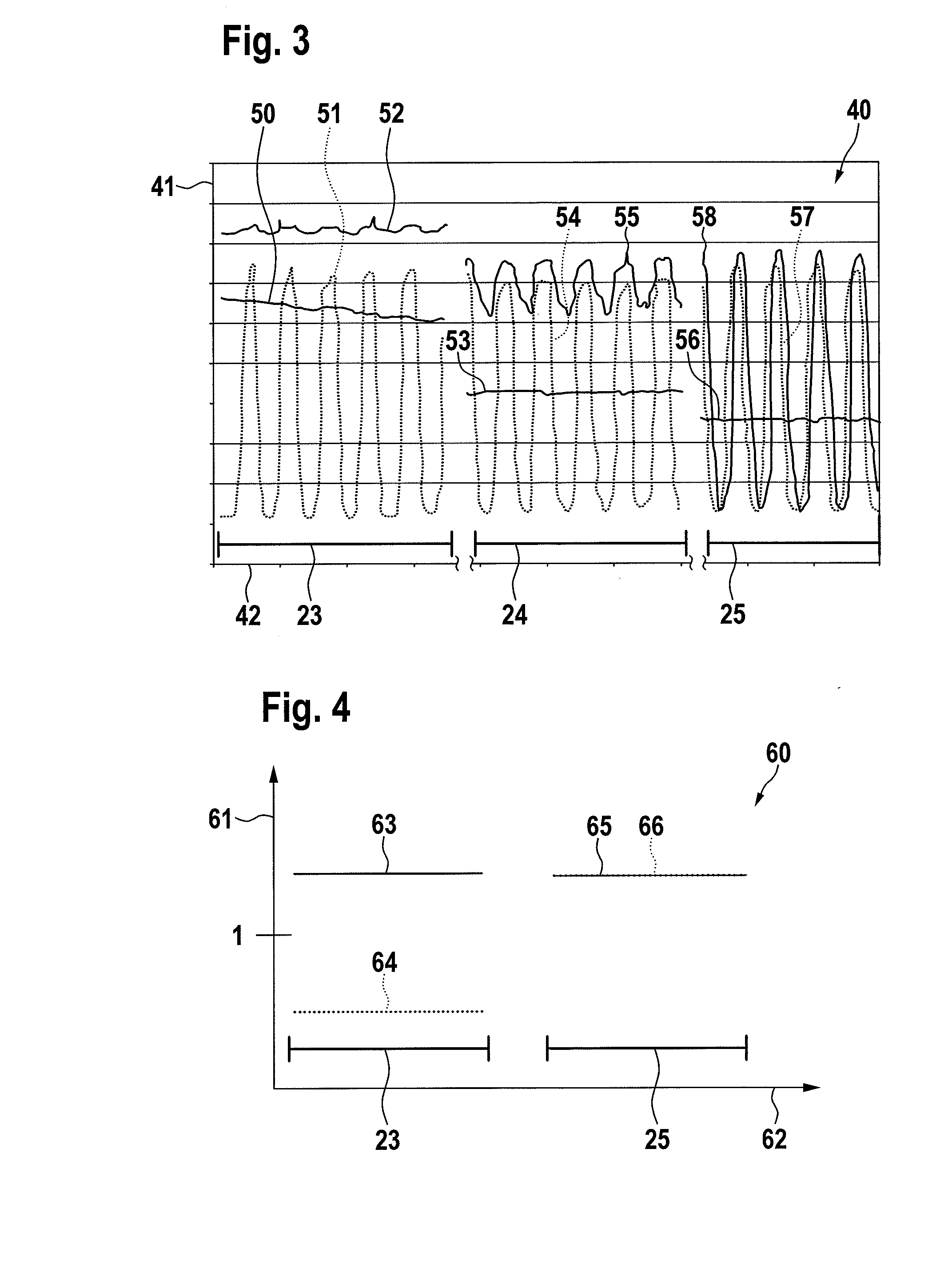
[0029]FIG. 3 is a signal flows during a regeneration of the particle filter when using two-point lambda probes in the exhaust gas duct,

[0030]FIG. 4 is a signal flows during a regeneration of the particle filter during a lean operating phase of the internal combustion engine.

DETAILED DESCRIPTION

[0031]FIG. 1 shows an internal combustion engine 10 having an air supply 11 and a particle filter 15 disposed in an exhaust gas duct 12 as well as a three-way catalytic converter 17 disposed downstream thereof. The exhaust gas of the internal combustion engine 10 purified in the particle filter 15 and the three-way catalytic conver...


PUM


Abstract

The invention relates to a method for monitoring and controlling the regeneration of a particle filter in an exhaust gas duct of an internal combustion engine, wherein said regeneration of the particle filter takes place by means of an oxidative burning off of particles during a regeneration phase. Provision is made according to the invention for the internal combustion engine to be operated at a lean operating point at least intermittently during lean operating phases or during a mixture oscillation and for the regeneration of the particle filter to be monitored during the lean operating phases or during the mixture oscillation via the temporal course of a second signal of a second lambda probe disposed in the exhaust gas direction downstream of said particle filter or of a second parameter derived therefrom in comparison to the temporal course of a first signal of a first lambda probe disposed in the exhaust gas direction upstream of said particle filter or of a first parameter derived therefrom. The invention also relates to a corresponding device. During the lean operating phases or the mixture oscillation, the first lambda probe disposed upstream of the particle filter emits a signal for a correspondingly lean lambda value. Oxygen is consumed from the exhaust gas by means of the oxidative burning off of particles in the particle filter. The oxygen concentration in the exhaust gas downstream of the particle filter is therefore lower than upstream of said particle filter. For that reason, the second lambda probe disposed downstream of said particle filter emits a signal for a richer lambda value in comparison to the first lambda probe during the lean operating phases or during the mixture oscillation. If the burn-off of particles has ended, the difference between the signals of the first and second lambda probe disappears.

Description

[0001]This application claims benefit of Serial No. 10 2009 028 237.8, filed 5 Aug. 2009 in Germany and which application is incorporated herein by reference. To the extent appropriate, a claim of priority is made to the above disclosed application.BACKGROUND[0002]The invention relates to a method for monitoring and controlling the regeneration of a particle filter in an exhaust gas duct of an internal combustion engine, wherein said regeneration of the particle filter occurs by means of an oxidative burning off of particles during a regeneration phase.[0003]The invention furthermore relates to a device for monitoring and controlling the regeneration of a particle filter in an exhaust gas duct of an internal combustion engine, the regeneration of the particle filter taking place by means of an oxidative burning off of particles during a regeneration phase and the control of the regeneration of said particle filter taking place via a control unit.[0004]Particle filters are used in th...

Claims


Application Information

Patent Timeline
IPC IPC(8): G01N7/00
CPCF01N3/035F01N11/007F02D41/1446F02D41/1441F02D41/0295
Inventor WEISS, EDUARDSTAVRIANOS, DIMITRIOS
Owner ROBERT BOSCH GMBH
Why Eureka
Try Eureka