
Bike shoe slipper

Inactive Publication Date: 2011-02-17
GALLAGHER FRANK
View PDF12 Cites 6 Cited by
  • Summary
  • Abstract
  • Description
  • Claims
  • Application Information

AI Technical Summary

Benefits of technology

[0008]The primary object of the invention is to provide a bike shoe slipper that easily attaches to cyclists shoes, providing protection to the cleats of the bike shoe while the wearer is walking.
[0009]Another object of the invention is to provide a bike shoe slipper that is elastic and can fit over a wide variety of shoe sizes.
[0011]A further object of the invention is to provide a bike shoe slipper that is light weight.
[0012]Yet another object of the invention is to provide a bike shoe slipper that rolls into itself to keep the dirty side of the sole from touching the inside of a cyclists pocket.
[0013]Still yet another object of the invention is to provide a bike shoe slipper that includes strap handles to help the user attach and detach the slipper from a bike shoe.

Problems solved by technology

When a person tries walking on a surface while wearing the cycling shoes, they risk damaging the cleats as well as damaging the surface of the floor that they are walking on.
One design for a cleat protector for cyclists has been put forth by R. Igor Crook in his U.S. Pat. No. 5,031,342 which describes a device that anchors on the nose of the cleat and heel box of the shoe, however this device is made of relatively rigid material and can only fit on a cyclists shoe of a specific size and cleat location.
However, there are deficiencies in the prior technology.
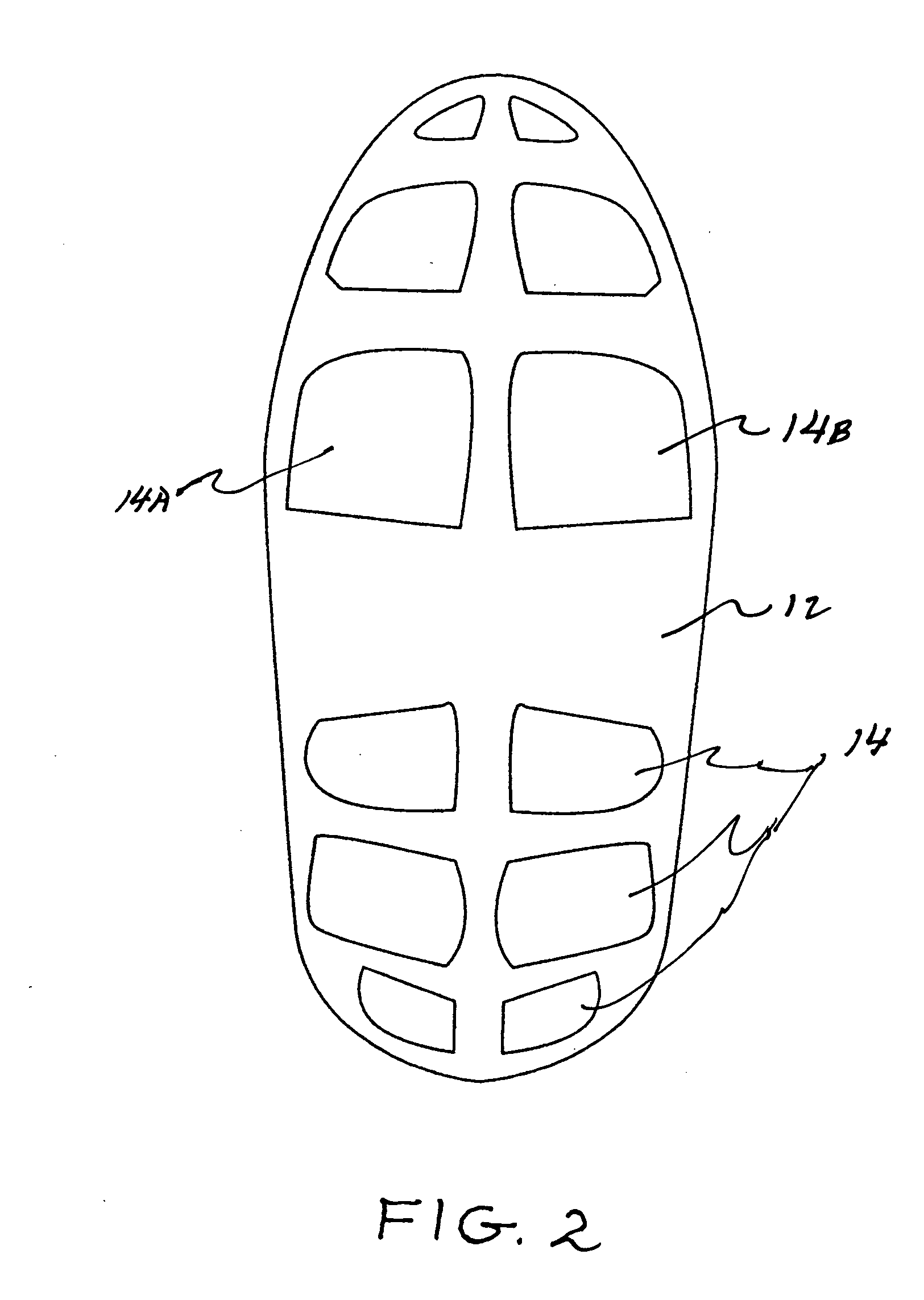
None of the devices described in prior art offer a fully elastic over-shoe type slipper that is made of very light weight elastic material, can fit on a variety of shoe sizes, can be rolled up into a small size for storage, can fit on either the left shoe or right shoe, and has a plurality of resilient pads fixed to the underside sole portion that align with the location of the cleats of a standard bicycle shoe.
Additionally, none of the prior art designs include a pair of strap handles located on the front and rear perimeter if the slipper opening to help a user attach or remove the slipper from a standard bicycle shoe.

Method used


Image

  • Bike shoe slipper
  • Bike shoe slipper
  • Bike shoe slipper

Examples


Embodiment Construction

[0023]Detailed descriptions of the preferred embodiment are provided herein. It is to be understood, however, that the present invention may be embodied in various forms. Therefore, specific details disclosed herein are not to be interpreted as limiting, but rather as a basis for the claims and as a representative basis for teaching one skilled in the art to employ the present invention in virtually any appropriately detailed system, structure or manner.

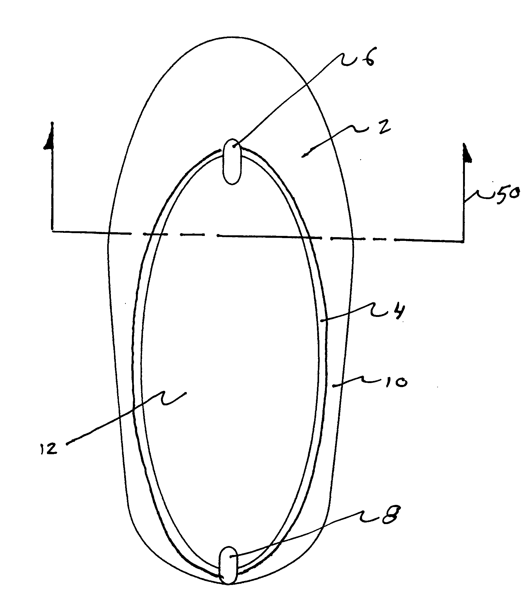
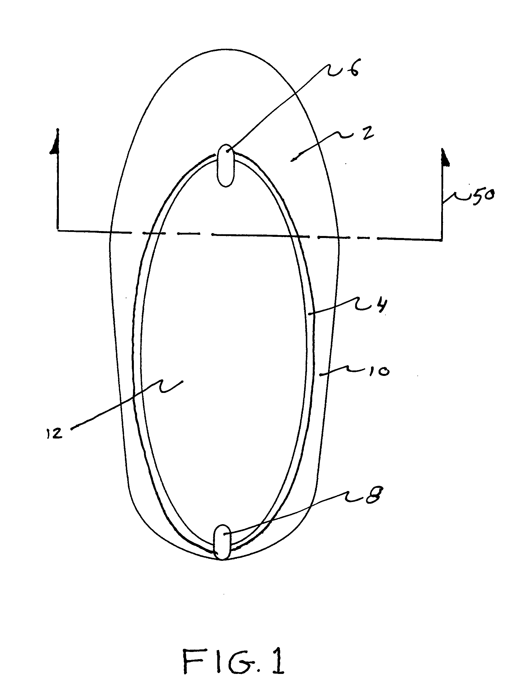
[0024]Referring now to FIG. 1 we see a top plan view of the present bike shoe slipper of the present invention. The construction is basically one piece where a sole portion 12, side walls 10 and a top portion 2 are sewn together from an elastic material such as spandex. An additional elastic band is sewn in around the perimeter 4 of the aperture on the top surface 2 where the user inserts his or her foot and cyclist's shoe. A front strap 6 and rear strap 8 are sewn onto the perimeter 4 to help the user slip the invention on and off o...


PUM


Abstract

A pair of bike shoe slippers, each slipper with a sole portion, a side wall portion and a top portion. The top portion including a shoe receiving aperture and the aperture including a sewn in elastic band that surrounds its perimeter. The over-slippers are constructed of elastic material such as spandex. The over-slippers each have a plurality of resilient pads fixedly attached to the underside of the sole portion of each slipper. The soles and the pads form a protective layer between the cleats of a standard bike shoe and any surface that the wearer of the bike shoe may be walking on. The pads of the slippers are located under the standard cleat locations found on a standard bike shoe. A preferred embodiment includes strap handles fixedly attached to the front and rear rim of the shoe receiving aperture to allow for easy attachment or removal of the slipper.

Description

CROSS REFERENCE TO RELATED APPLICATIONS[0001]Not ApplicableSTATEMENT REGARDING FEDERALLY SPONSORED RESEARCH OR DEVELOPMENT[0002]Not ApplicableDESCRIPTION OF ATTACHED APPENDIX[0003]Not ApplicableBACKGROUND OF THE INVENTION[0004]This invention relates generally to the field of shoe accessories and more specifically to a bike shoe slipper.[0005]Many modern day bicyclists wear cycling shoes that include cleats on their soles that engage with a mating receiving member located on a bicycle pedal. When a person tries walking on a surface while wearing the cycling shoes, they risk damaging the cleats as well as damaging the surface of the floor that they are walking on. To this end it would be advantageous to wear some sort of slipper or attachment that would attach to the cycling shoe and provide protection for the cleats.[0006]The concept of placing a slipper or over-shoe on and around a primary shoe is well known. Rubber slippers have been in existence for many years and are used to prot...

Claims


Application Information

Patent Timeline
IPC IPC(8): A43B5/00A43B3/16
CPCA43B5/185
Inventor GALLAGHER, FRANK
Owner GALLAGHER FRANK
Learn More