
Interface, apparatus, and method for communication between a radio eqipment control node one or more remote radio equipment nodes

a radio equipment and communication node technology, applied in the direction of electrical equipment, time-division multiplex, multiplex communication, etc., can solve the problems of complex time delay calibration for multi-hop configuration, additional challenges for multi-hop configuration,

Active Publication Date: 2011-02-10
TELEFON AB LM ERICSSON (PUBL) +3
View PDF10 Cites 98 Cited by
  • Summary
  • Abstract
  • Description
  • Claims
  • Application Information

AI Technical Summary

Benefits of technology

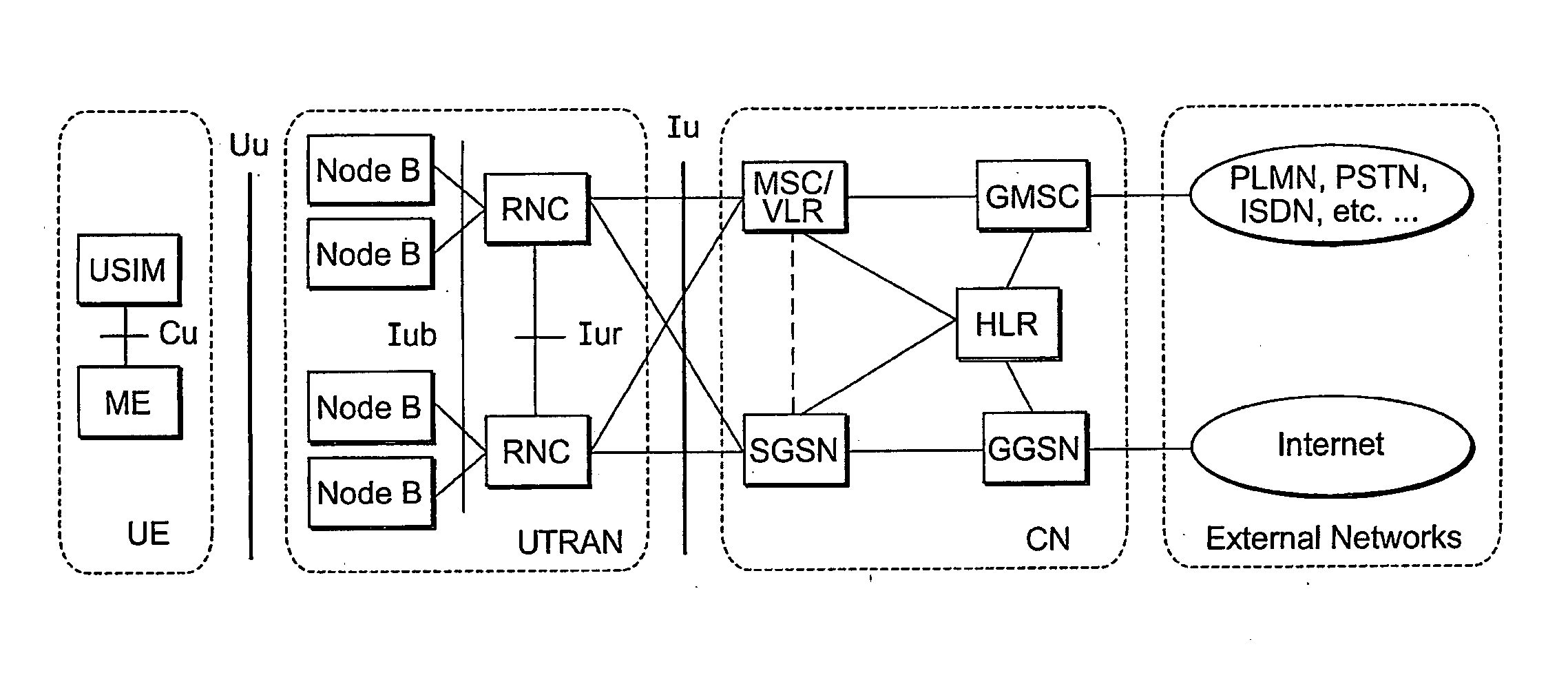
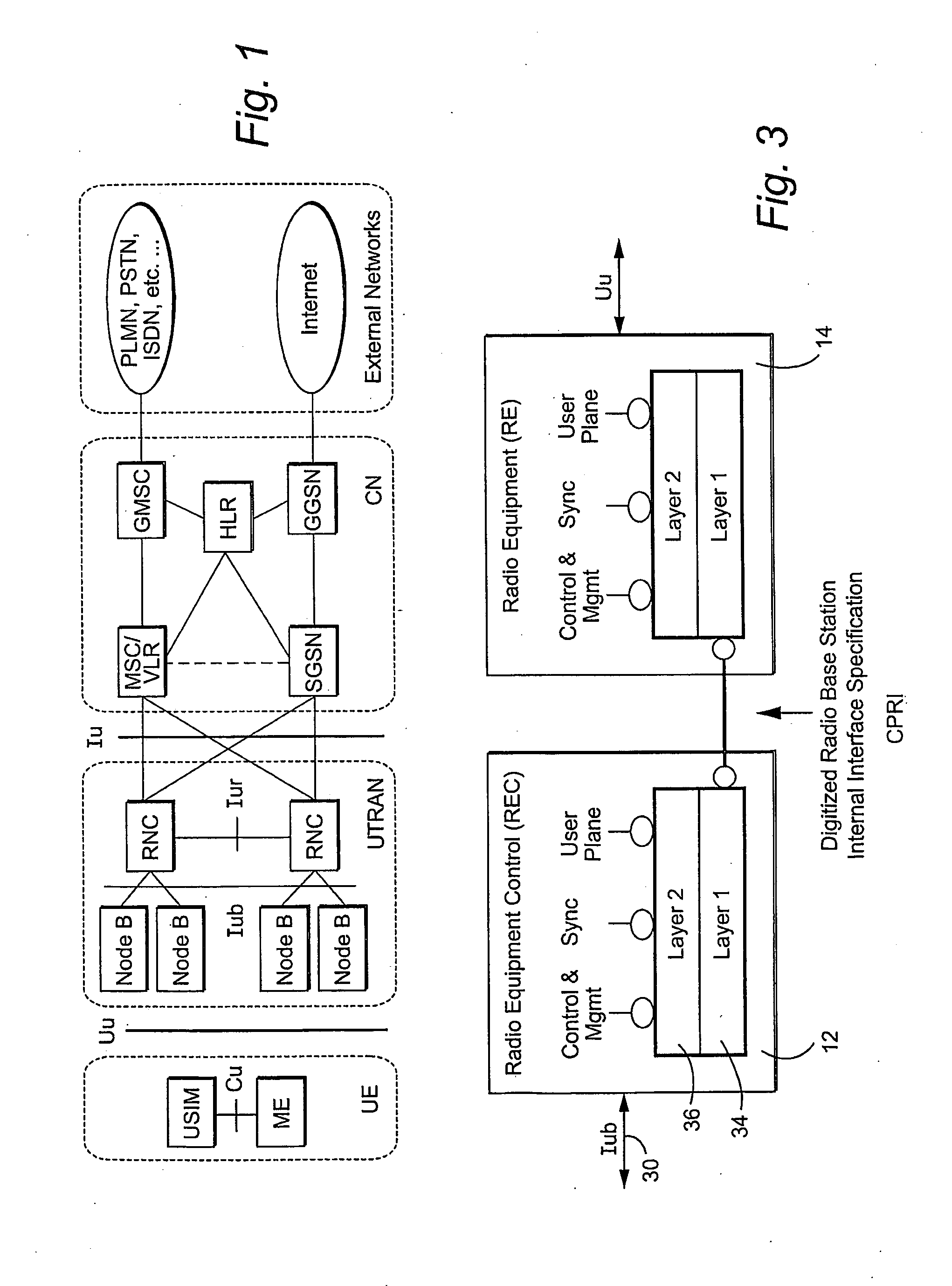
[0003]In a typical cellular radio system, wireless user equipment units (UEs) communicate via a radio access network (RAN) with one or more core networks. The user equipment units (UEs) can be mobile stations such as mobile telephones (“cellular” telephones) and laptops with mobile termination, and thus can be, for example, portable, pocket, hand-held, computer-included, or car-mounted mobile devices which communicate voice and / or data with radio access network. Alternatively, the wireless user equipment units can be fixed wireless devices, e.g., fixed cellular devices / terminals which are part of a wireless local loop or the like.

Problems solved by technology

Multi-hop configurations present additional challenges as compared to single hop configurations, particularly in the area of synchronization.
Time delay calibration for multi-hop configuration is more complicated than for single hop.

Method used


Image

  • Interface, apparatus, and method for communication between a radio eqipment control node one or more remote radio equipment nodes
  • Interface, apparatus, and method for communication between a radio eqipment control node one or more remote radio equipment nodes
  • Interface, apparatus, and method for communication between a radio eqipment control node one or more remote radio equipment nodes

Examples


Embodiment Construction

[0049]The following description sets forth specific details, such as particular embodiments, procedures, techniques, etc., for purposes of explanation and not limitation. But it will be appreciated by one skilled in the art that other embodiments may be employed apart from these specific details. For example, although the following description is facilitated using non-limiting examples, the present invention may be employed to in any type of radio communications system where base stations are used. In some instances, detailed descriptions of well-known methods, interfaces, circuits, and signaling are omitted so as not obscure the description with unnecessary detail. Moreover, individual blocks are shown in some of the figures. Those skilled in the art will appreciate that the functions of those blocks may be implemented using individual hardware circuits, using software programs and data, in conjunction with a suitably programmed digital microprocessor or general purpose computer, u...


PUM


Abstract

An interface, apparatus, and method are described for communication between a radio equipment control (REC) node and first and second radio equipment (RE) nodes in a radio base station that transceives information over radio interface using multiple antenna carriers. The REC node is separate from and coupled to the first RE node by a first transmission link, and the second RE node coupled to the first RE by a second transmission link. Both control information and user information intended for communication between the REC node and the first RE node and the REC and the second RE node are conveyed over the first transmission link. The first RE node also conveys information between the REC and second RE node. Many advantageous features are described.

Description

RELATED APPLICATIONS[0001]This application claims priority from U.S. provisional patent application No. 60 / 617,084, filed on Oct. 12, 2004, entitled “Common Public Radio Interface (CPRI): Interface Specification (version 2.),” the contents of which is incorporated herein by reference. The application also claims priority from and is a continuation-in-part of PCT application serial number PCT / IB2004 / 003170, filed on Sep. 29, 2004, entitled “Interface, Apparatus & Method for Communication between a Radio Equipment Control Node and A Remote Radio Equipment Node in a Radio Base Station,” the contents of which is incorporated herein by reference.TECHNICAL FIELD[0002]The present invention is directed to distributed radio base stations where a base station includes a main baseband processing unit coupled to one or more remote radio units where RF processing occurs, and in particular, to the radio interface between the main baseband processing unit and the one or more remote radio units.BAC...

Claims


Application Information

Patent Timeline
Patent Type & Authority Applications(United States)
IPC IPC(8): H04J3/00H04B7/216H04J3/06H04W88/08H04W92/12
CPCH04J3/0682H04W88/085H04J3/0691
Inventor AARFLOT, TORBJOMOSTERLING, JACOBOSTMAN, THOMASSPLETT, ARMINKRONER, HANSMERZ, PETERKORTE, WERNERKRAMER, ROLFHASSLER, BERNDLAGRANGE, PATRICKGEORGEAUX, ERICSATO, TOSHIFUMINAWATA, HIZURUYAGAWA, KENICHIOGANGHUA, YANGHAIQING, LANZHIBIN, LIN
Owner TELEFON AB LM ERICSSON (PUBL)
Learn More