Eureka AIR delivers breakthrough ideas for toughest innovation challenges, trusted by R&D personnel around the world.

Method and Apparatus For Removal Of Oil From Utility Gas Stream

Active Publication Date: 2011-02-10
EXXONMOBIL UPSTREAM RES CO
View PDF102 Cites 97 Cited by
  • Summary
  • Abstract
  • Description
  • Claims
  • Application Information

AI Technical Summary

Problems solved by technology

Environmentally conscious and efficient recovery of oil and gas from hydrocarbon reservoirs is a multidimensional problem that has become one of the world's toughest energy challenges.
The vapor generally can not be filtered out and at high pressures filtration of entrained droplets is typically inefficient.
This cylinder oil “carry-over” into the seal gas is expected to damage and cause premature failure of standard dry seal compressors, resulting in significant down-time and lost production.
Purifying a slip stream taken from the high pressure discharge of the dry seal compressor is technically challenging.
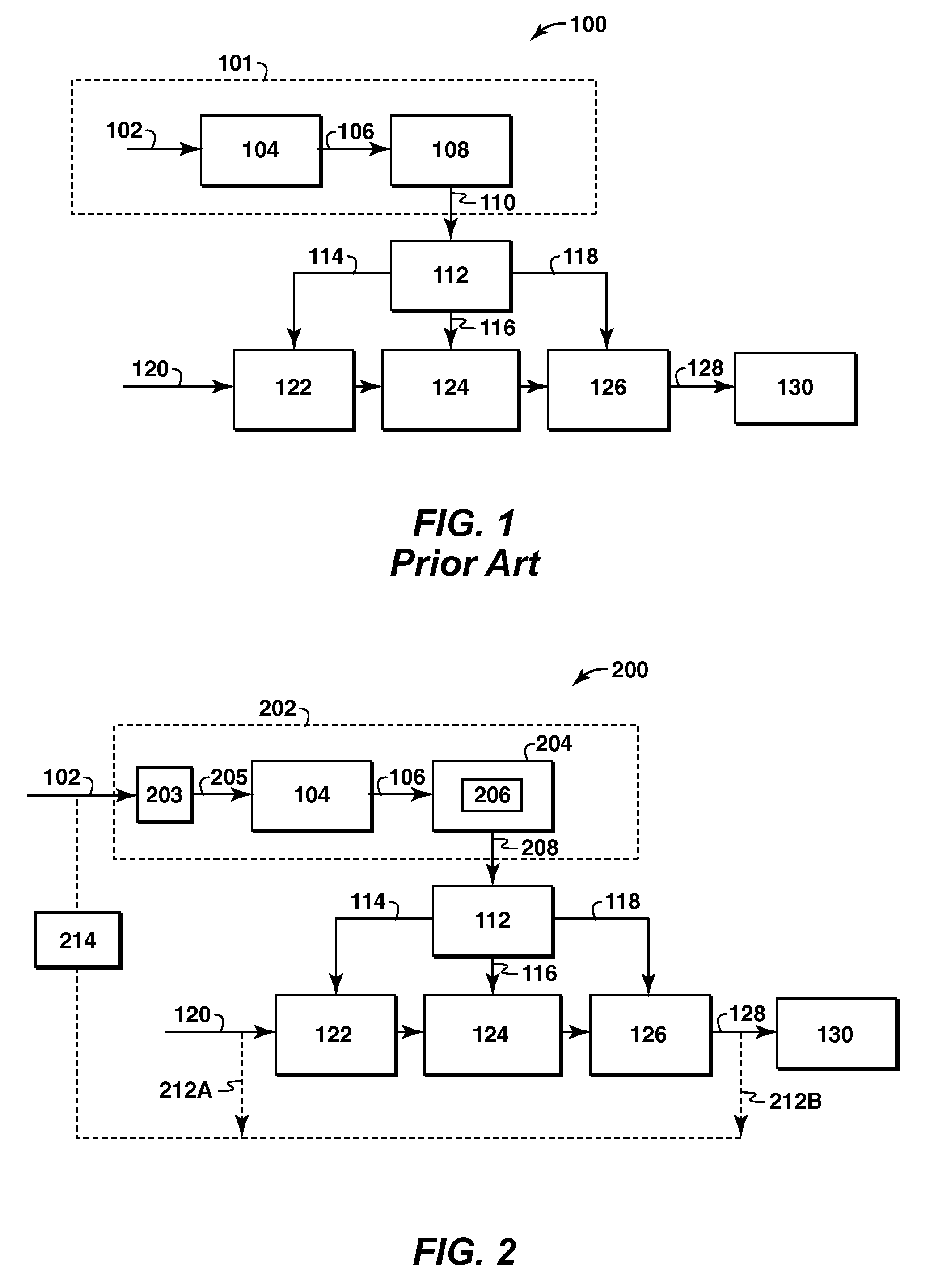
This requires additional process and separation units to generate the fuel gas and a separate seal gas booster compressor (e.g. a reciprocating compressor), which can itself be a source of oil and particulate contamination.
Reciprocating compressors of this type are typically lubricated with cylinder oil that has some miscibility with the gas, especially at high pressures.
Thus, it can not be filtered out at high pressure but condenses or “drops out” of the gas when the pressure is dropped through the seals or at pressure regulators that control the pressure to the seals.
This cylinder oil “carry-over” into the seal gas may damage and cause premature failure of standard DGS's.
Such results are good, but even a small amount of oil can damage a DGS and cause significant downtime.

Method used


Image

  • Method and Apparatus For Removal Of Oil From Utility Gas Stream
  • Method and Apparatus For Removal Of Oil From Utility Gas Stream
  • Method and Apparatus For Removal Of Oil From Utility Gas Stream

Examples


example 1

Example of Fuel Gas Composition that Will Not Condense in the Seals

[0085]Sources of seal gas can include any convenient extraction point in a gas production or treating process, such as at compressor discharge, as long as the discharge pressure is greater than the suction pressure of the compressor being sealed (i.e., the pressure needed to form a dry gas seal in a compressor). When the pressure of the gas is lowered (e.g., throttling across the seal), the temperature can drop such that some of the seal gas condenses.

[0086]FIG. 7 illustrates an exemplary graph comparing the phase envelopes of a treated seal gas and an untreated seal gas. The graph 700 relates pressure 702 in bar absolute (bara) and enthalpy 704 in kilo-calories per kilogram moles (kcal / kg·mol). A phase envelope of an untreated gas 706 is shown along with line 708 indicating an isenthalpic throttling of the untreated gas 706 across the seal. The exemplary seal gas 706 is taken from compressor discharge at 388 bara an...

example 2

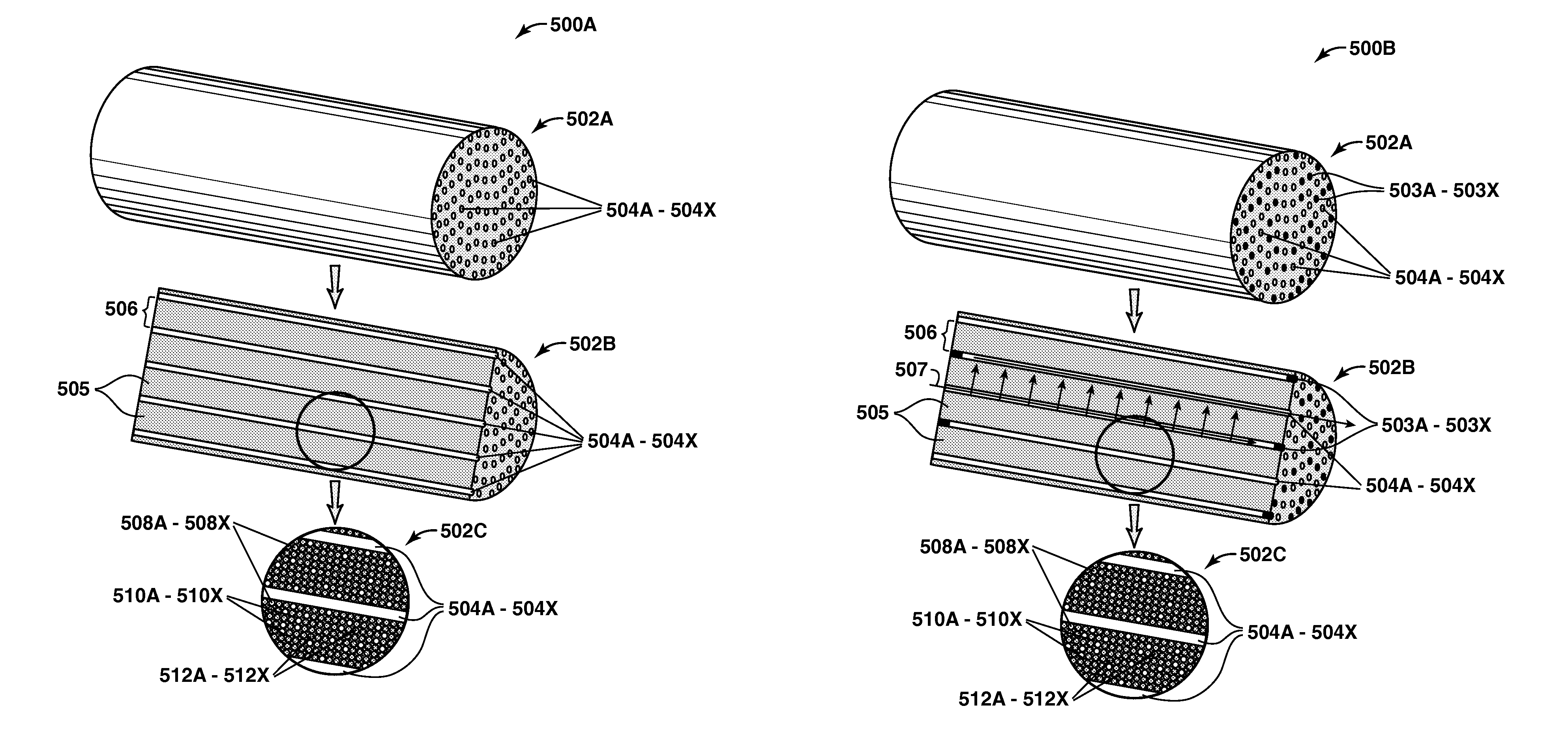
[0088]The shape of the adsorption front that moves through a parallel channel contactor 500A during the oil adsorption step is modeled. This modeling used a competitive Langmuir isotherm to predict the loading of oil in the adsorbent 505. For the targeted adsorbents, the adsorption strength (e.g. selectivity) of the oil is expected to be so large that a sharp or shock wave like adsorption front moves through the contactor 500A. This type of behavior allows the adsorbent volume in the contactor 500A to be used efficiently, minimizing the adsorbent volume required and maximizing the length of an adsorption cycle.

[0089]This model simulates a single channel 504A of a solid adsorbent 506 without open mesoporous voids, open macropores, or heat adsorbing material. Due to symmetry it is sufficient to model a single channel 504A. The modeling follows an oil adsorption front that moves through the contactor 500A in an adsorption step 306 that follows after a calcination step 308. After the ca...

example 3

[0092]To establish conditions under which oil could be calcined, a 2 gram sample of mesoporous MCM-41 zeolite was loaded with about a 1,900 gram / mole polyglycol compressor oil. The zeolites were loaded by contacting the MCM-41 zeolite with the polyglycol oil in an amount close to incipient wetness. This required approximately 0.24 grams of oil. To further reduce the amount of oil that is not adsorbed in the zeolite the samples were placed in a vacuum oven and held at 125° C. for 12 hours at a pressure of less than 1 millimeter of mercury (mmHg)—about 0.00133 bar. When the samples were removed from the vacuum oven the amount of oil adsorbed was found to be greater than 10 wt % of the sample mass. To measure the rate at which this oil can be removed by calcination, thermogravimetric (TGA) experiments were performed. The batch of oil containing MCM-41 material was divided into about 2 to about 25 milligram (mg) samples that were repetitively placed in the TGA. The TGA was operated with...


PUM

PropertyMeasurementUnit
Temperatureaaaaaaaaaa
Fractionaaaaaaaaaa
Pressureaaaaaaaaaa

Abstract

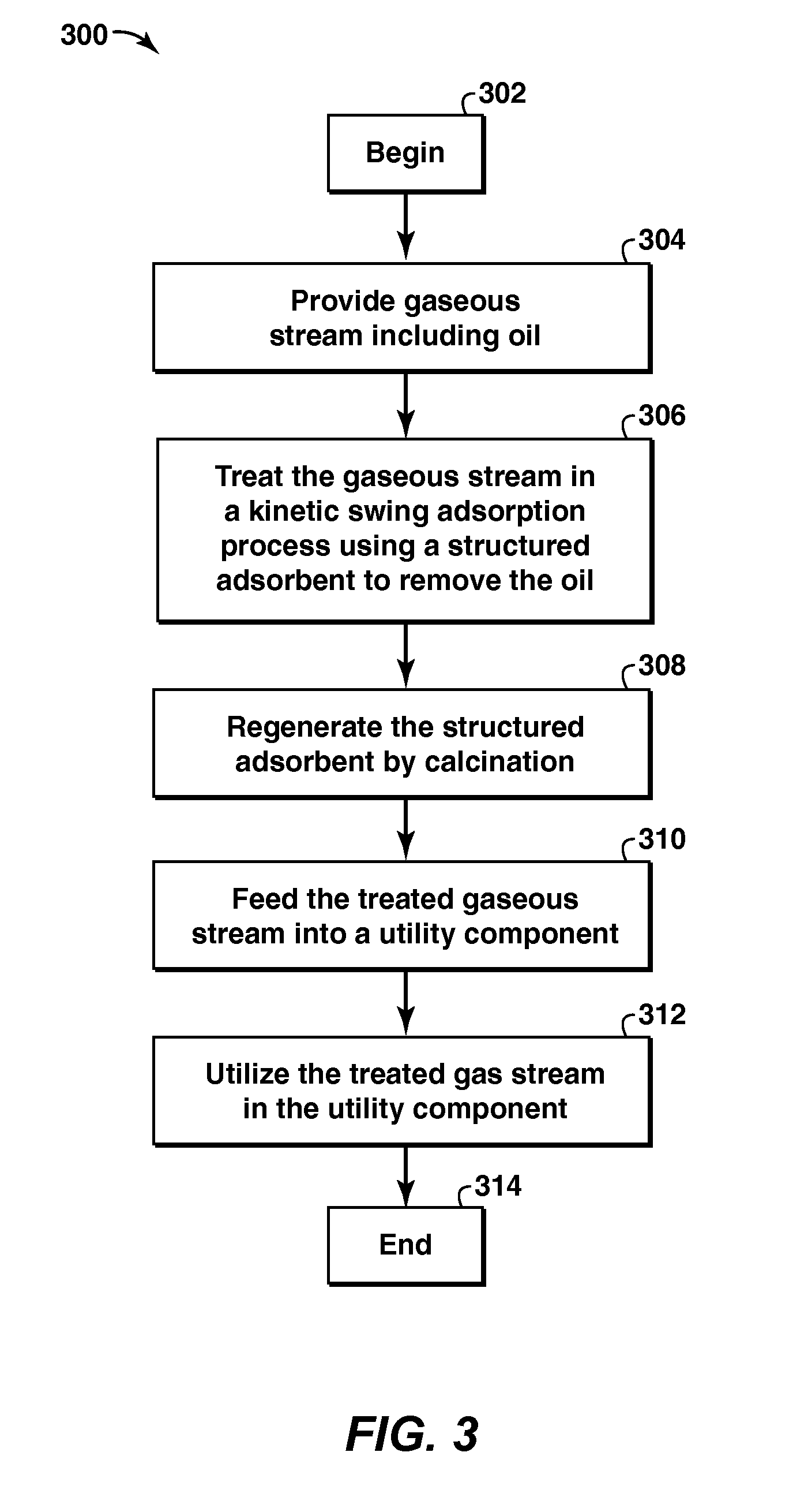
The present application is directed to a method and system for preparing gaseous utility streams from gaseous process streams, particularly, removing oil contamination from such streams prior to use in a dry gas seal. The methods and systems may include at least one kinetic swing adsorption process including pressure swing adsorption, temperature swing adsorption, calcination, and inert purge processes to treat gaseous streams for use in dry gas seals of rotating equipment such as compressors, turbines and pumps and other utilities. The adsorbent materials used include a high surface area solid structured microporous and mesoporous materials.

Description

CROSS REFERENCE TO RELATED APPLICATIONS[0001]This application claims the benefit of U.S. Provisional Application No. 61 / 125,939, filed 30 Apr. 2008.FIELD OF THE INVENTION[0002]This invention relates generally to methods of processing gaseous slip streams. More specifically, the invention relates to a process and apparatus for removing oil from a process slip stream used as a utility gas in a utility component.BACKGROUND[0003]This section is intended to introduce the reader to various aspects of art, which may be associated with exemplary embodiments of the present invention, which are described and / or claimed below. This discussion is believed to be helpful in providing the reader with information to facilitate a better understanding of particular techniques of the present invention. Accordingly, it should be understood that these statements are to be read in this light, and not necessarily as admissions of prior art.[0004]Environmentally conscious and efficient recovery of oil and ...

Claims


Application Information

Patent Timeline
IPC IPC(8): B01D53/047B01D3/00
CPCB01D53/04B01D53/0462B01D53/047B01D53/0473B01D2259/40088B01D2253/108B01D2253/1085B01D2253/342B01D53/0476F04D29/124B01D2253/104Y02C20/40B01D53/0438B01D53/0407B01D2257/70B01D2253/102B01D2253/1124B01D2253/204B01D2253/20
Inventor DECKMAN, HARRY W.KAMAKOTI, PREETIRAVIKOVITCH, PETER I.KELLEY, BRUCE T.NORTHROP, PAUL SCOTTRASMUSSEN, PETER C.TANAKA, PAUL LAWRENCEWEBSTER, MARTIN N.ROTH, WIESLAW JERZYCORCORAN, EDWARD W.
Owner EXXONMOBIL UPSTREAM RES CO
Why Eureka
Eureka Blog
Learn More