
Solar energy panel frame and installation system device thereof

a solar energy panel and installation system technology, applied in the direction of solar heat collector mounting/support, solar heat collector safety, light and heating apparatus, etc., can solve the problems of not only difficult cleaning, but also heavy economic loss, and achieve low cost, simple structure, and high

Inactive Publication Date: 2011-01-06
WU WENXIANG +1
View PDF7 Cites 41 Cited by
  • Summary
  • Abstract
  • Description
  • Claims
  • Application Information

AI Technical Summary

Benefits of technology

[0008]The objective of the present invention is to provide a solar energy panel frame and an installation system device to solve the above-described problems, wherein the solar energy panel frame has a self-cleaning function, and the installation system device is installed conveniently, high efficiently and safely.
[0025]Comparing with the prior art, the present invention can achieve the following advantages:
[0026]Firstly, to install an automatic cleaning device in the frame is propitious to bring the product performance into full play. This new idea and simple structure lead to low cost and high effects.
[0027]Secondly, the invention is designed according to the solar panel's structure and installation feature, which is convenient and time saving. It not only increases the installation's efficiency but has a safety performance, which reduces the cost and saves materials further.

Problems solved by technology

However, the dust and the bird manure will be accumulated on the surface of the solar panels which are set outdoors, and the winter snow is also accumulated on the surface in winter in the high latitude area.
As a result, the light receiving efficiency of the solar panels is low.
According to the experiments, the amount of dust accumulated in three months will make the generated energy fall off one third, which will directly cause heavy economic loss.
However, it's not only hard for cleaning, but also inefficiency and with high costs.
It's inadvisable to use the angle iron joint on the roof because the angle iron are heavy.
It's also needed boring lots of holes both in the angle iron and the solar energy panel frame, which is a difficult procedure and make the angle irons easily rust that can not ensure the duration of service.
However, in the use of standard aluminum profile, the construction and installation feature of the solar energy panel frame is not taken into account.
The installation parts are basically bolts and nuts; punching holes in the frame is needed and the procedure is not only trouble but time-consuming, which undermine the installation's effectiveness.

Method used


Image

  • Solar energy panel frame and installation system device thereof
  • Solar energy panel frame and installation system device thereof
  • Solar energy panel frame and installation system device thereof

Examples


first embodiment

[0043]The first embodiment is as follows.

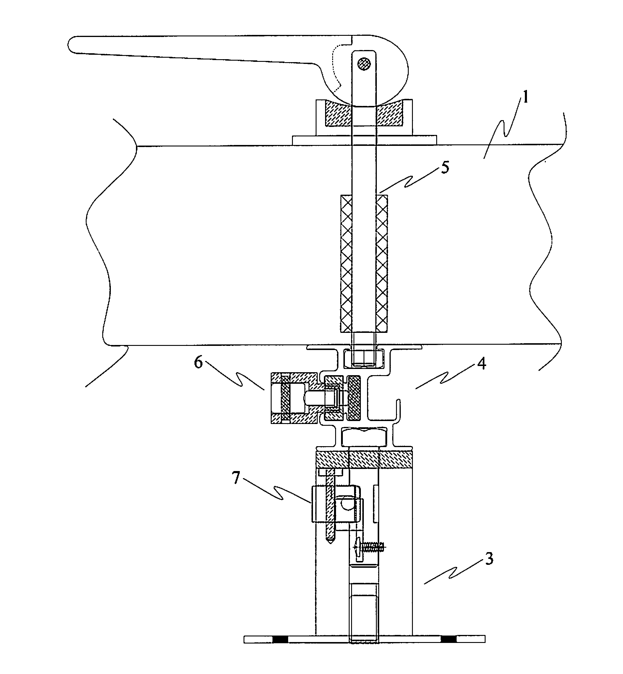
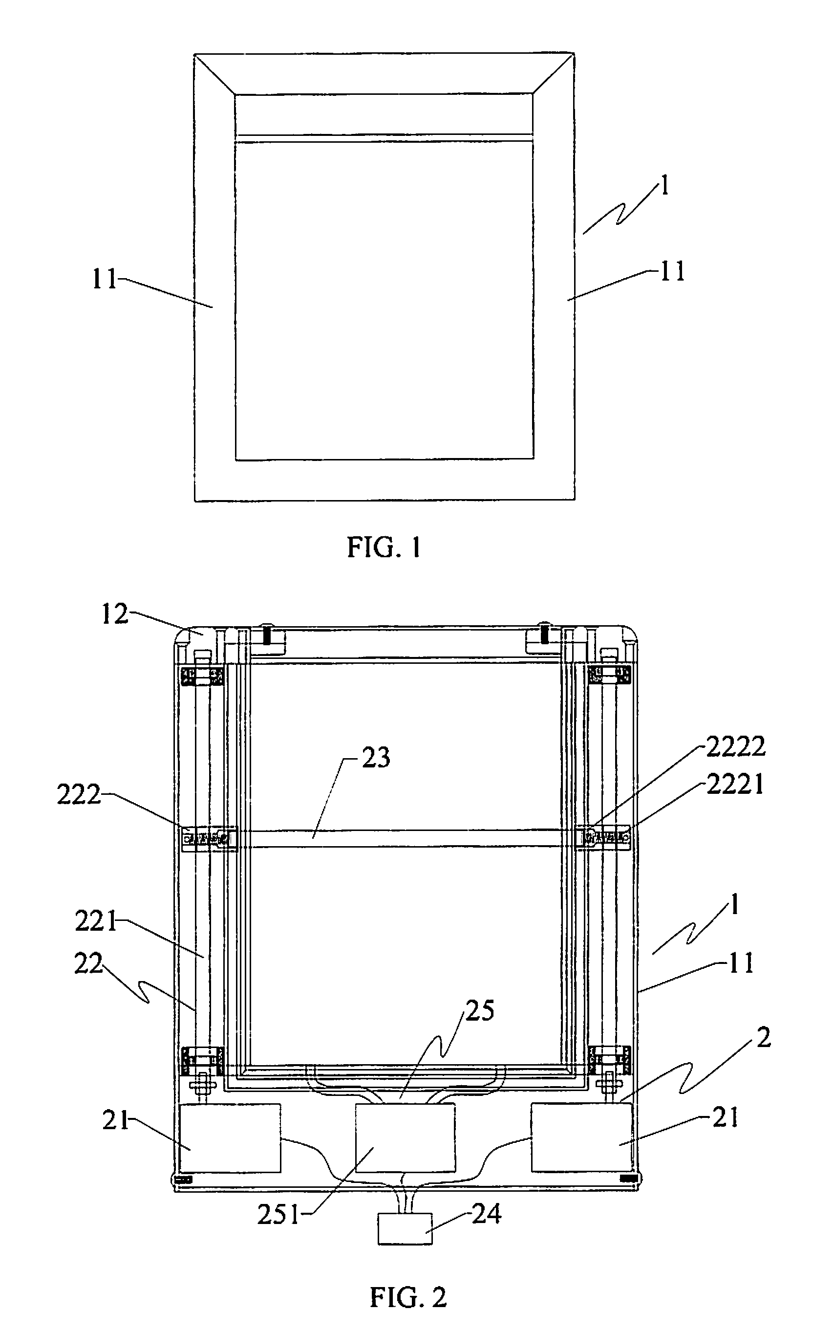
[0044]Referring to FIG. 1 to FIG. 3, a solar energy panel frame according to a first embodiment of the present invention includes a frame body 1 which is consisted of a plurality of profile brackets 11 abutting joint to each other. A connector 12 is set on the abutting joint of said profile bracket 11. The connector 12 can be a slab rubber for avoiding a water leakage of the profile brackets 11 in long time exposed to the sun and rain. A sealant tape 13 is set on the junction between the profile bracket and the solar energy panel to prevent dust and water fog in the air to soak in.

[0045]Said frame body 1 has an automatic cleaning device 2. The automatic cleaning device 2 includes a synchronous reversible motor 21 set on the profile bracket 11, a screw transmission mechanism 22 driven by the output shaft of the motor, a cleaning brush 23 driven to move up and down by said screw transmission mechanism 22, and a remote control integrated circuit...

second embodiment

[0062]The second embodiment is as follows.

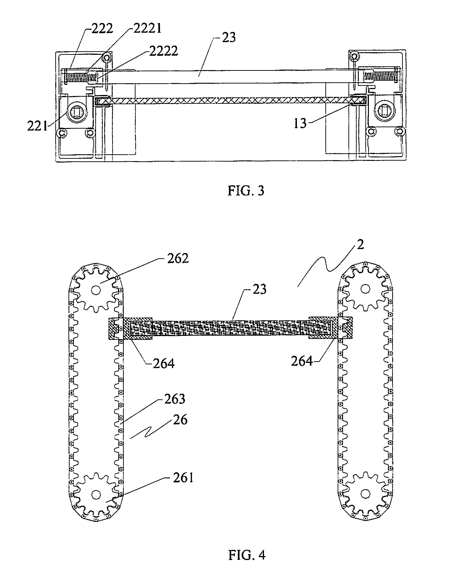
[0063]Referring to FIG. 4, an automatic cleaning device 2 according to a second embodiment of the present invention is similar to the first embodiment. However, the automatic cleaning device 2 in this embodiment includes a synchronous reversible motor 21 set on the profile bracket 11, a sprocket-chain transmission mechanism 26 driven by the output shaft of the motor, a cleaning brush 23 driven to move in up and down by said screw transmission mechanism 22, and a remote control integrated circuit system 24. Said sprocket-chain transmission mechanism 26 includes a first sprocket 261 and a second sprocket 262 which is set on the two ends of the profile bracket separately, a chain 263 set on said two sprockets and a fixed connection block 264 which is fixedly connected on the chain. Said first sprocket 261 is fixedly connected to the output shaft of the motor. Said cleaning brush 23, whose two ends are connected to the chain 263 separately by sa...


PUM


Abstract

The present invention disclosed a solar energy panel frame and installation system device there of. Said solar energy panel frame includes a frame body which is consist of a plurality of profile brackets abutting joint to each other. Wherein an automatic cleaning device is set on said frame body. And said automatic cleaning device comprises a motor located in the profile bracket symmetrically, a transmission mechanism connected to the output shaft of the motor, a cleaning brush moved in upper and lower direction by said transmission mechanism which it connected to, and a remote control integrated circuit system. Said installation system device of the solar energy panel frame includes a pedestal, a rail bracket which is fixedly connected to the pedestal by a bracket fixing part, and a frame fixing part which is used to lock up the solar energy panel. Wherein said rail bracket is consist of a plurality of profiles having a grooved rail which is on the match usage with above component parts, and said bracket fixing part and said frame fixing part are both eccentric rotary locking solid structure.

Description

PRIORITY[0001]This application claims priority to an application filed with the Chinese Intellectual Property Office on Jul. 3, 2009 and assigned Serial No. 200910040877.2, the contents of which are incorporated herein by reference.BACKGROUND OF THE INVENTION[0002]1. Field of the Invention[0003]The present invention relates to the field of solar energy photovoltaic product technology, and more particularly to solar energy panel frame and installation system device thereof.[0004]2. Description of the Related Art[0005]In these days, as the energy resources are becoming deficient, every country puts forth effort to develop the new energy more and more rapidly. The solar energy, which is a new cleaning energy, plays an important role in the new energy research and development area all over the world. It's known that the basic theory of a solar energy photovoltaic generation is receiving the luminous energy from the outside solar panels, and then transforming the luminous energy to elect...

Claims


Application Information

Patent Timeline
IPC IPC(8): H01L31/048F24S90/00
CPCF24J2/461F24J2/5203F24J2/5245H02S20/00F24J2/526Y02E10/47Y02E10/50F24J2/5256H02S30/10H02S40/10F24S25/61F24S25/30F24S25/65F24S40/20F24S25/634
Inventor WU, WENXIANGLIU, WEIFENG
Owner WU WENXIANG
Learn More