Lockup device and fluid type power transmitting device

Active Publication Date: 2011-02-10
EXEDY CORP
View PDF11 Cites 47 Cited by
  • Summary
  • Abstract
  • Description
  • Claims
  • Application Information

AI Technical Summary

Benefits of technology

[0011]An object of the present invention is to provide a lockup device that can improve a fuel efficiency of a vehicle.
[0013]With this lockup device, when the piston is pressed against the input rotary member using oil pressure, the power is transmitted from the input rotary member to the output rotary member through the piston and the output member. If a rotational sped fluctuation is imparted to the input rotary member, then the rotational speed fluctuation is transmitted to the output rotary member through the output member. Since the inertia member is connected to the output member through the second elastic member, the rotational speed fluctuation is damped by the inertia member and the second elastic member. Thus, the inertia member and the second elastic member function as a dynamic damper. By adjusting an inertia amount of the inertia member and a stiffness of the second elastic member, a rotational speed fluctuation damping effect can be increased in a region of low rotational speeds. In other words, with this lockup device, the lockup region can be expanded and the fuel efficiency of a vehicle can be improved.
[0019]Since this fluid type power transmitting device is equipped with a lockup device according to any one of the first to fifth aspects, the vibration damping performance can be improved.

Problems solved by technology

However, the lockup device presented in Japanese Patent Publication Number 3542186 is designed to be used only during normal travel of a vehicle and cannot easily secure an acceptable vibration damping performance at, for example, low traveling speeds.
That is, the conventional lockup device cannot accommodate an expanded lockup region and it is difficult to improve the fuel efficiency of a vehicle using the conventional lockup device.

Method used


Image

  • Lockup device and fluid type power transmitting device
  • Lockup device and fluid type power transmitting device
  • Lockup device and fluid type power transmitting device

Examples


Embodiment Construction

[0024]Embodiments of the present invention will now be explained with reference to the drawings.

Overall Configuration of Torque Converter

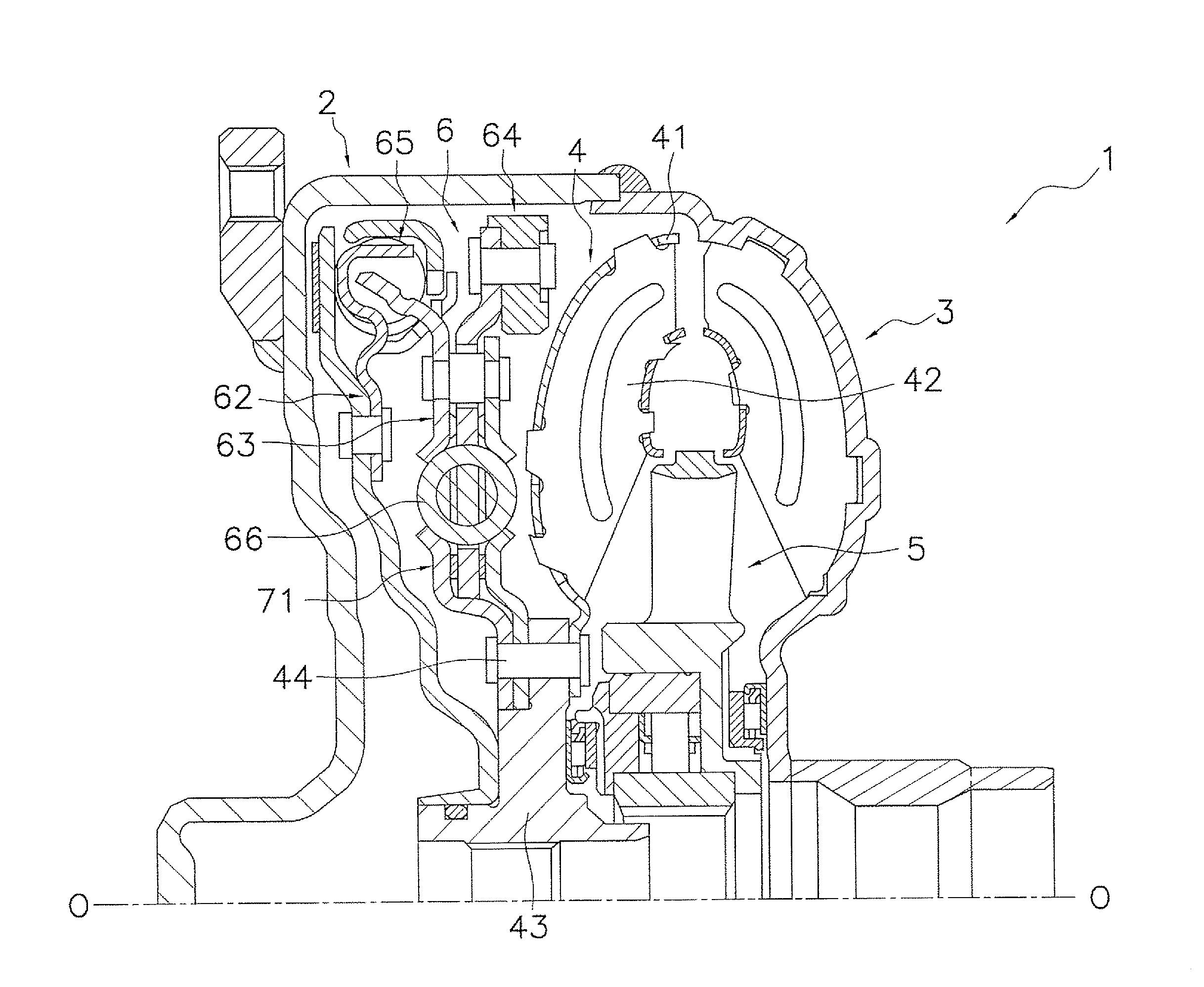
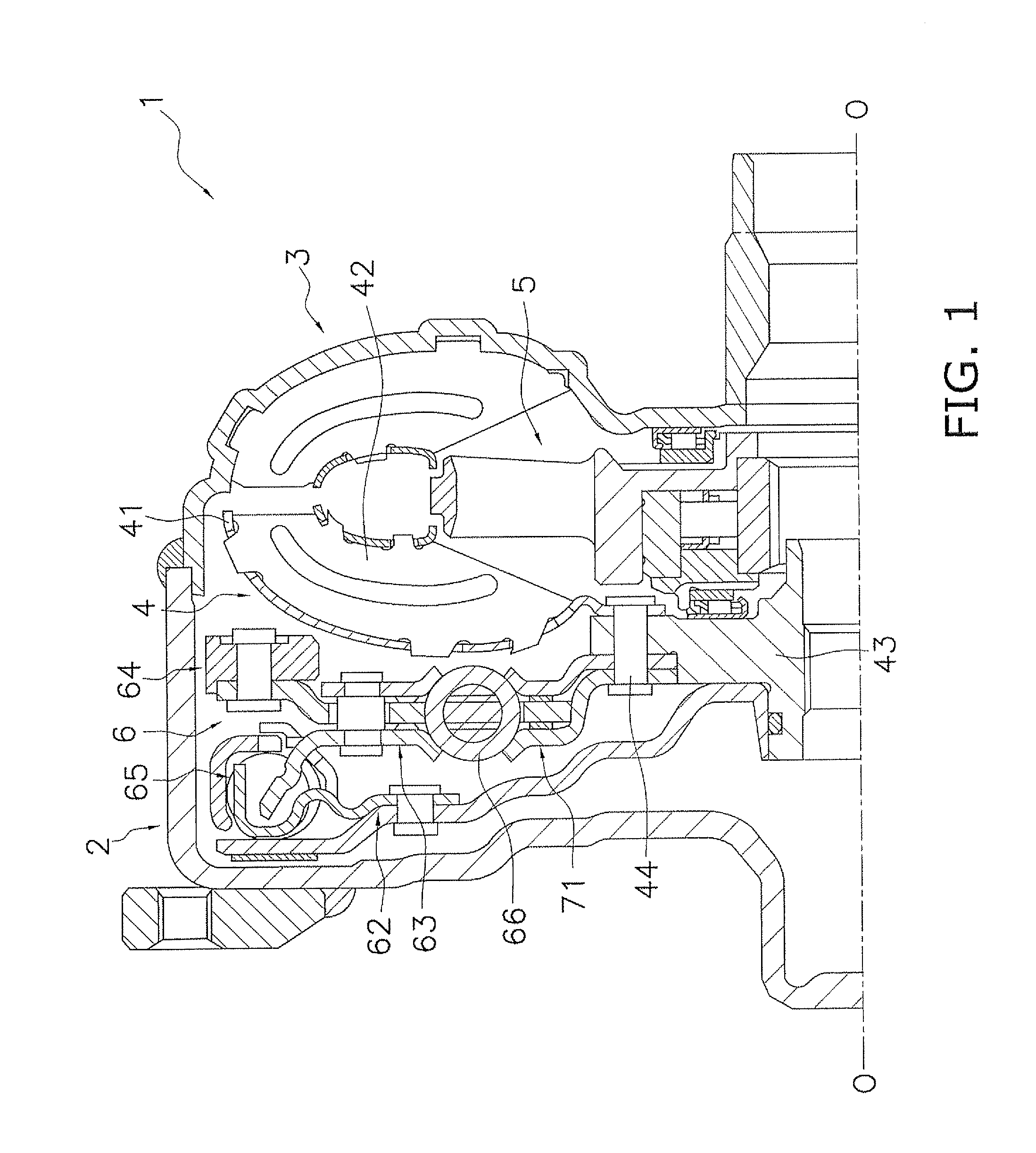
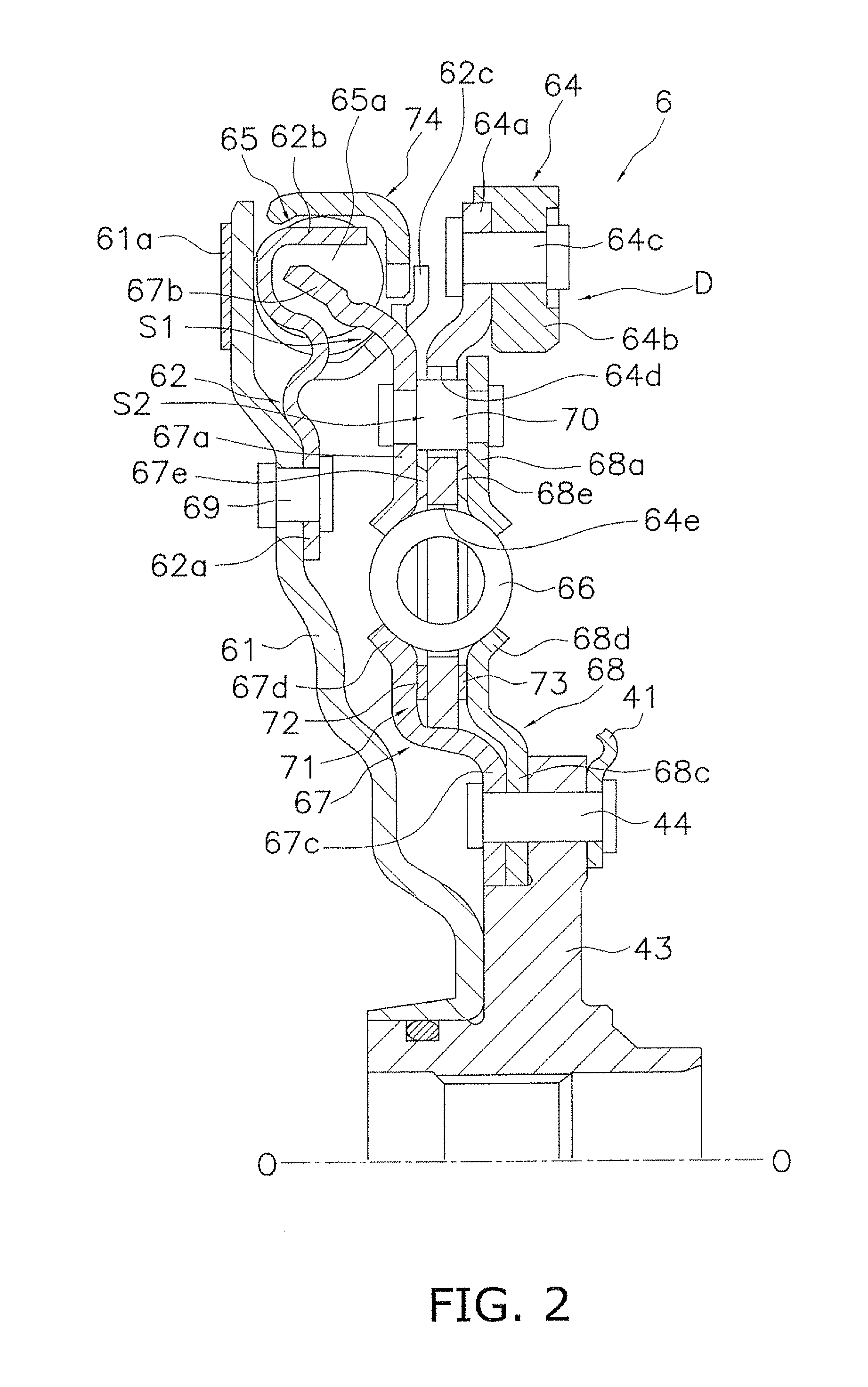
[0025]A torque converter 1 exemplifying a fluid type power transmitting device will now be explained using FIGS. 1 and 2. FIG. 1 is a vertical cross sectional schematic view of the torque converter 1. FIG. 2 is a vertical cross sectional schematic view of a lockup device 6. An engine (not shown) is arranged on a left-hand side of FIG. 1 and a transmission (not shown) is arranged on a right-hand side of FIG. 1. The line O-O shown in FIG. 1 indicates a rotational axis of the torque converter 1.

[0026]The torque converter 1 is a device for transmitting power from a crankshaft (not shown) of the engine to an input shaft of the transmission and chiefly includes a front cover 2 (input rotary body) to which power is inputted, an impeller 3, a turbine 4 (output rotary body), a stator 5, and a lockup device 6.

[0027]The front cover 2 is fixed to the impeller ...


PUM


Abstract

The object of the invention is to provide a lockup device that can improve a fuel efficiency of a vehicle. The lockup device (6) has a piston (61), an output plate (63), a first coil spring (65), an inertia member (64), and a second coil spring (66). The output plate (63) is coupled to a turbine (4) such that it can rotate as an integral unit with the turbine (4). The first coil spring (65) elastically couples the piston (61) to the output plate (63) in a rotational direction. The inertia member (64) is provided such that it can rotate relative to the output member (63). The second coil spring (66) elastically couples the inertia member (64) to the output plate (63) in a rotational direction.

Description

CROSS-REFERENCE TO RELATED APPLICATIONS[0001]This U.S. National stage application claims priority under 35 U.S.C. §119(a) to Japanese Patent Application No. 2008-146306, filed in Japan on Jun. 3, 2008, the entire contents of which are hereby incorporated herein by reference.BACKGROUND[0002]1. Technical Field[0003]The present invention relates to a lockup device used in a fluid type power transmitting device.[0004]2. Background Information[0005]A known example of a fluid type power transmitting device is a torque converter equipped with a lockup device. The lockup device is a mechanism serving to connect mechanically a front cover and a turbine together and is arranged in a space between the front cover and the turbine. The lockup device allows torque to be transmitted directly from the front cover to the turbine.[0006]A conventional lockup device has a piston and a damper mechanism. The piston is arranged such that it can move in an axial direction. When the piston is pushed against...

Claims


Application Information

Patent Timeline
IPC IPC(8): F16H45/02
CPCF16H45/02F16H2045/0205F16H2045/0294F16H2045/0263F16H2045/0231
Inventor MATSUOKA, YOSHIHIROYAMAGUCHI, MITSUGUKAWAMOTO, TAKESHIYAMASHITA, KAZUHIROOOMOTO, KAZUAKI
Owner EXEDY CORP
Why Eureka
Try Eureka