
Write-erase endurance lifetime of memory storage devices

a memory storage device and write-erase technology, applied in the field of write-erase endurance lifetime of memory storage devices, can solve the problems of flash memory blocks eventually wearout, flash memory will exhibit high latency, performance penalty for additional read and write operations, etc., and achieve the effect of improving the write-erase endurance lifetime of flash-based ssd

Active Publication Date: 2011-02-03
SK HYNIX INC
View PDF8 Cites 69 Cited by
  • Summary
  • Abstract
  • Description
  • Claims
  • Application Information

AI Technical Summary

Benefits of technology

[0008]The present invention provides a method and system that improves the write-erase endurance lifetime of a flash-based SSD via a combination of data placement, garbage collection and wear-leveling processes.

Problems solved by technology

If write-in-place is used instead, flash will exhibit high latency due to the necessary reading, erasing and reprogramming (i.e., writing) of the entire block in which the data is being updated.
Relocate-on-write necessitates a garbage collection process which results in a performance penalty for additional read and write operations.
Flash memory blocks eventually wear out with progressing number of write-erase cycles until they can no longer be erased or written.
The SSD device may eventually die with a number of unconsumed cycle budget left when garbage collection can no longer return a free block, referred to as “wear-leveling insufficiency”.
Uneven wear-out of flash memory blocks is mainly due to spatial localities in workloads.
The wear-out of blocks gradually becomes increasingly unbalanced.
However, the endurance lifetime of the SSD device depends not only on wear-leveling but also data placement and garbage collection.

Method used


Image

  • Write-erase endurance lifetime of memory storage devices
  • Write-erase endurance lifetime of memory storage devices
  • Write-erase endurance lifetime of memory storage devices

Examples


Embodiment Construction

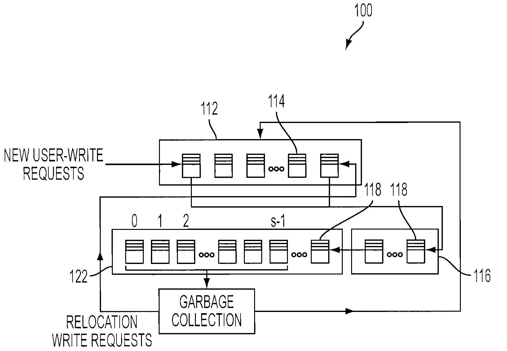
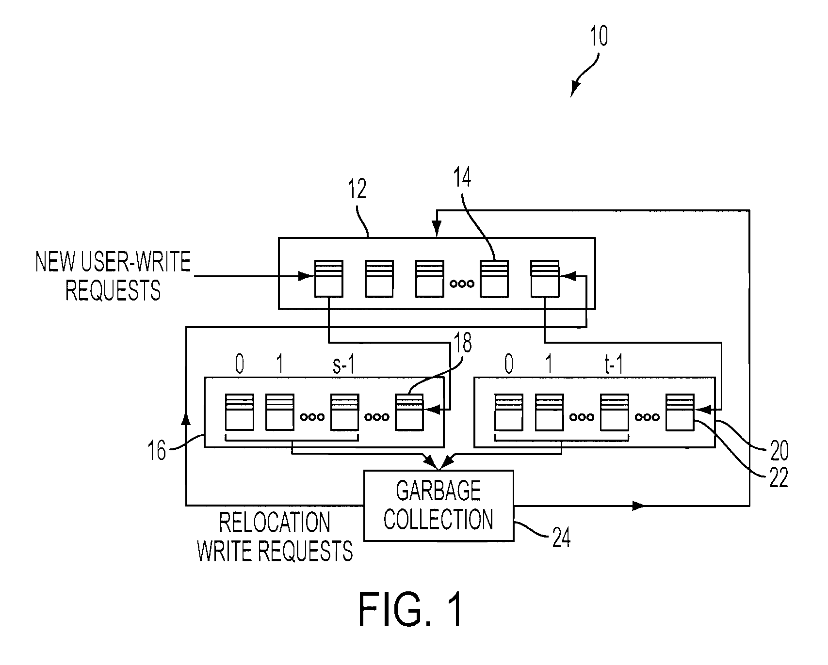
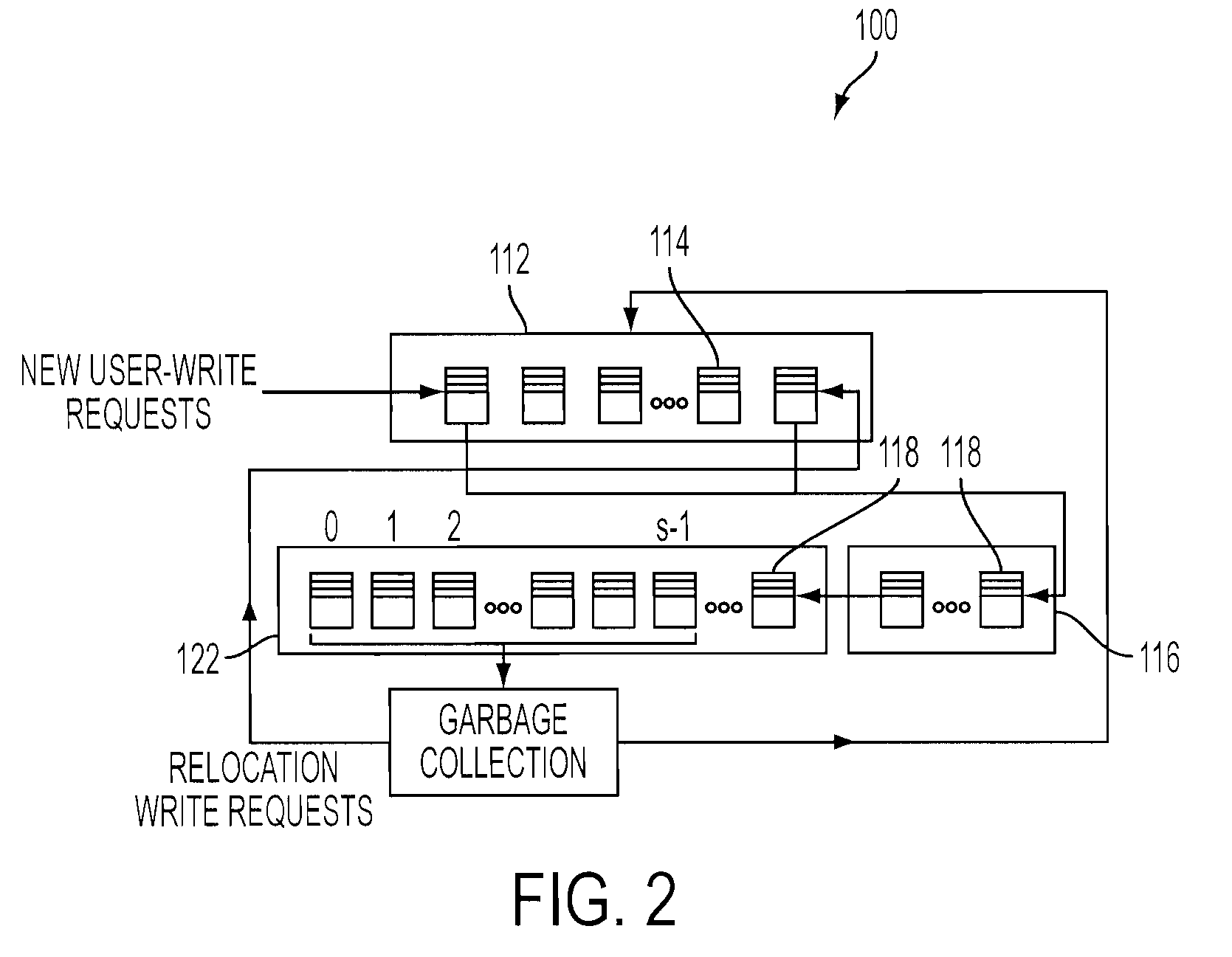
[0019]With reference now to FIG. 1, there is a flash memory management system that can be implemented within an embodiment of the present invention. One embodiment of the present invention uses data placement, garbage collection and wear-leveling processes based on separation and prediction to improve the write-erase endurance lifetime of a flash-based SSD device. The system 10 dynamically separates blocks with dynamic data pages from blocks with static data pages (i.e., pages with fewer updates) based on the prediction that dynamic data tends to wear out blocks faster than those with static data and therefore the dynamic data pages are placed on younger blocks which have the lower block write-erase endurance cycle count (i.e., the higher remaining unconsumed cycle count) and static data pages are placed on older blocks whenever possible.

[0020]As shown in FIG. 1, a memory management system 10 for a memory device of a computer (as depicted in FIG. 4) is provided. The system 10 includ...


PUM


Abstract

A memory management system and method for managing memory blocks of a memory device of a computer. The system includes a free block data structure including free memory blocks for writing, and sorting the free memory blocks in a predetermined order based on block write-erase endurance cycle count and receiving new user-write requests to update existing data and relocation write requests to relocate existing data separately, a user-write block pool for receiving youngest blocks holding user-write data (i.e., any page being updated frequently) from the free block data structure, a relocation block pool for receiving oldest blocks holding relocation data (i.e., any page being updated infrequently) from the free block data structure, and a garbage collection pool structure for selecting at least one of user-write blocks and relocation blocks for garbage collection, wherein the selected block is moved back to the free block data structure upon being relocated and erased.

Description

BACKGROUND[0001]The present invention relates to data storage devices, and more specifically, to a memory management system and method for improving write-erase endurance lifetime of a flash-based solid state drive (SDD) device via data placement, garbage collection and wear-leveling processes.[0002]Currently, SSD devices based on NAND-flash memories are used as the primary storage in computer architecture, ranging from notebooks to enterprise storage systems. These devices provide random I / O performance and access latency that are orders of magnitude better than that of rotating hard-disk drives (HDD). Moreover, SSDs significantly reduce power consumption and dramatically improve robustness and shock resistance. NAND-flash memories are organized in terms of blocks, where each block consists of a fixed number of pages and the block is the elementary unit for an erase operation, whereas reads and writes are processed in terms of pages. Before data can be written to a page (the page i...

Claims


Application Information

Patent Timeline
IPC IPC(8): G06F12/02G06F12/00
CPCG06F12/0246G06F2212/1044G06F2212/7205B62D35/001G11C16/349G11C16/3495G06F2212/7211
Inventor HU, XIAO-YUELEFTHERIOU, EVANGELOS S.HAAS, ROBERT
Owner SK HYNIX INC
Learn More