Circuit board based connector with raised projection section

Active Publication Date: 2011-02-03
ADVANCED FLEXIBLE CIRCUITS
View PDF5 Cites 7 Cited by
  • Summary
  • Abstract
  • Description
  • Claims
  • Application Information

AI Technical Summary

Benefits of technology

Thus, an objective of the present invention is to provide a circuit board based connector, which effectively improves the drawbacks of the conventional connectors in respect of complicated manufacturing process, high cost molds, and being unable to eliminate external electromagnetic interference.
Another objective of the present invention is to provide a circuit board based connector that features a raised projection section, which is formed by means of substrate bonding and formation techniques, whereby signal transmission between male and female portions of a connector assembly is made precise and undesired detachment between the portions is prevented.
With the technical solution adopted in the present invention, a connector is provided with a projection section of a predetermined height, so as to allows a shielding layer and the projection section that are provided on a circuit substrate of the connector to matingly engage and thus fix in a connection socket. Further, the connector in accordance with the present invention is simpler than a conventional connector in respect of structure and manufacturing process and is also cheaper than the conventional connector.
Further, the connector of the present invention comprises shielding layers that drain signals associated with external electromagnetic interference to a circuit board connected thereto to provide excellent shielding effect.
In respect of being compact, the connector of the present invention is particularly suitable for a device that requires fine pitch of terminals and small size. For a regular small-sized electronic product, signal transmission is often realized through connection between a connector of the type discussed herein and a counterpart connection socket. The present invention provides a structure of plug type connector by means of substrate bonding and stacking techniques, which forms a connector comprises a circuit board jumper structure. The present invention reduces the manufacturing costs of a plug type connector and allows for mass production through the conventional circuit substrate manufacturing process.

Problems solved by technology

However, in mating with a connection socket, since the contact surface of an insertion end of a conventional connector and the contact surface of the connection socket are both flat surfaces, the resulting mating force therebetween is generally insufficient, whereby the conductive terminals of the connector and the connection socket are susceptible to disengagement from each other, leading to instability of the electrical connection.
This makes the conventional connector that is equipped with an additional retention structure suffering the disadvantages of complicated structure, high cost of molds, and tedious assembling process.
Further, the conventional connector is not capable of effectively eliminating external electromagnetic interference due to incomplete shielding and poor grounding.
Consequently, the conventional connector often suffers noise induced in the transmission of signal between circuit systems, which adversely affects the quality of signal.

Method used


Image

  • Circuit board based connector with raised projection section
  • Circuit board based connector with raised projection section
  • Circuit board based connector with raised projection section

Examples


first embodiment

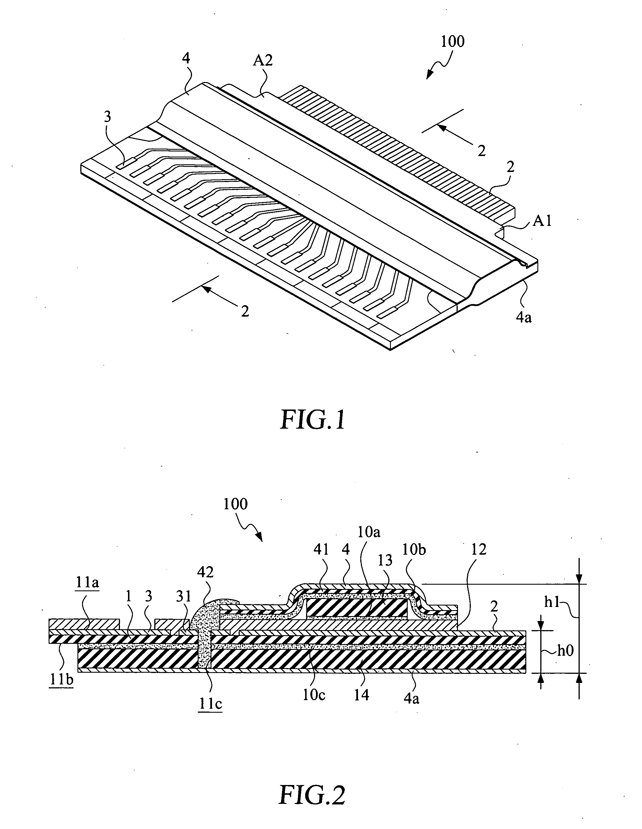
With reference to the drawings and in particular to FIGS. 1 and 2, of which FIG. 1 shows a perspective view of a first embodiment in accordance with the present invention and FIG. 2 shows a cross-sectional view taken along line 2-2 of FIG. 1, the present invention provides an circuit board based connector with raised projection section, generally designated at 100. The circuit board based connector 100 comprises a circuit substrate 1. The circuit substrate 1 has a first surface 11a and a second surface 11b. An end of the circuit substrate 1 is provided with a plurality of spaced conductive terminals 2. The circuit substrate 1 also has an end opposite to the conductive terminals 2 and provided with a plurality of spaced flat cable connection terminals 3.

The circuit substrate 1 is covered with an insulation layer 12. Bonded atop the insulation layer 12 with an adhesive layer 10a is at least one projection section 13, which is raised above a reference datum plane defined by the first s...

fourth embodiment

The first shielding layer 4 and the fourth shielding layer 4c are connected to each other through a via 11e and solder 44 and are also in electrical connection with a grounding pattern 31 preset in the circuit substrate 1, or are connected through a via 11f that carries a conductive substance 45 (see FIG. 9 that shows a cross-sectional view of a circuit board based connector 100d in accordance with the present invention) and also in electrical connection with a grounding pattern 32 preset in the circuit substrate 1.

fifth embodiment

FIG. 10 is a cross-sectional view of a fifth embodiment in accordance with the present invention. The embodiment provides a circuit board based connector 100e that is applicable to a double-sided circuit substrate. Namely, the second surface 11b of the circuit substrate 1 has an undersurface that forms a conductive layer 18 and an insulation layer 12a. The insulation layer 12a has an undersurface that is bonded to a substrate 14b with an adhesive layer 10g and a fourth shielding layer 4c is formed on an undersurface of the substrate 14b. In this embodiment, the insulation layer 12a does not completely covers or overlaps the whole conductive layer 18 and at least one flat cable connection terminal 18a is formed on the undersurface of the conductive layer 18 at a selected location.

To connect flat cables to the connector 100e, the conductive terminals of a flat cable can be bonded to the flat cable connection terminals 3 with solders, or the conductive terminals of another flat cable c...


PUM


Abstract

Provided is a circuit board based connector with raised projection section, which is formed by applying substrate bonding and formation techniques to make a connector that features a raised projection section. The circuit substrate has an end that is provided with conductive terminals and an opposite end that is provided with flat cable connection terminals for connection with a flat cable. The circuit substrate has a first surface on which the projection section is formed. A shielding layer covers the projection section and a portion of the first surface. The circuit substrate has a second surface on which a second shielding layer is selectively formed. When the circuit substrate is inserted into an insertion space defined in a connection socket with the conductive terminals thereof, the shielding layer and the projection section of the circuit substrate are put into engagement with and thus retained by the insertion space of the connection socket to thereby fix within the connection socket.

Description

FIELD OF THE INVENTIONThe present invention relates to an electrical connector, and in particular to a circuit board based connector with raised projection section, which is formed by applying substrate bonding and formation techniques.BACKGROUND OF THE INVENTIONConnectors are commonly incorporated in the layout of circuit for various electrical equipments, such as computers, mobile phones, digital cameras, global positioning systems (GPSs), liquid crystal display (LCD) panel, and measuring instruments and controlling devices, for connecting a signal cable, a coaxial cable, or a flat cable to a circuit board, a circuit module, or an electrical device to realize transmission of electrical signals. A regular connector comprises conductive terminals that form electrical engagement with contacts included in a circuit layout on a circuit board to form electrical connection.A conventional connector comprises conductive terminals and flat cable connection terminals. The conductive terminal...

Claims


Application Information

Patent Timeline
IPC IPC(8): H01R13/62
CPCH05K1/0218H05K1/117H05K1/141H01R12/79H05K2201/10189H05K2201/10356H05K2201/2036H05K2201/0715
Inventor CHUO, CHIH-HENGLIN, GWUN-JINSU, KUO-FU
Owner ADVANCED FLEXIBLE CIRCUITS
Why Eureka
Try Eureka