Multiplexed nanoscale electrochemical sensors for multi-analyte detection
a multi-analyte, electrochemical sensor technology, applied in the field of electrochemical sensors, can solve the problems of large, complex devices, and the size and complexity of such devices, and achieve the effect of reducing the cost of optical detection and portability, and reducing the cost of operation and maintenan
- Summary
- Abstract
- Description
- Claims
- Application Information
AI Technical Summary
Problems solved by technology
Method used
Image
Examples
example 1
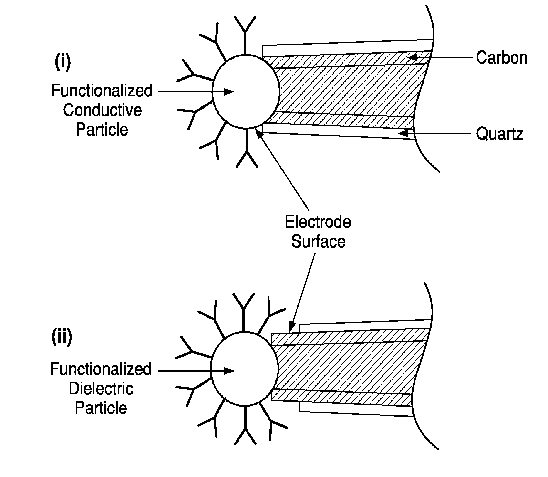
[0103]A carbon nano-capillary was brought into a contact with a dilute solution of suspended nanoparticles with diameters slightly larger than the inner diameter of the carbon capillary. The solution penetrated the carbon capillary by capillary suction and a particle locked into place by Van der Waals forces, as depicted in FIG. 11(i) (schematic view) and FIG. 11(ii) (actual image of particle—a magnetic bead—locked into place). Rigorous washings failed to detach the particle. Subsequently, the solvent trapped inside the bore of the carbon capillary evaporated. It was determined that either conducting or dielectric particles were suitable for this application. The process is applicable to mounting particles adorned with appropriate functionalities, e.g., ligands, antibodies or oligonucleotides.
example 2
[0104]One method of fabricating the sensing devices of the instant invention is the directed assembly method. This method permits the positioning of particular particles adjacent or directly adjacent to particular electrodes, and eliminates the need for post-attachment analysis to determine which particles are adjacent to which electrodes.
[0105]The directed assembly can be performed using dielectrophoresis. To perform directed assembly, an electrode probe, such as a nano-scale capillary, is brought into contact with a dilute suspension of particles. A director electrode is then positioned opposite the electrode probe, and an alternating (AC) potential difference is applied between the nano-scale capillary and the director electrode. In the presence of the resulting, non-uniform electric field, one or more particles polarize and migrate towards the location of the maximum field intensity, at the opening of the nano-scale capillary. After the particle migrates to the nano-scale capill...
example 3
[0110]To characterize the electrochemical behavior of the particle-electrode sensors, the contact resistance between the functionalized particle and the carbon nanopipe and the overall resistance of the particle-tipped electrode is measured. The using the probe for electrochemical detection is tested by using a sandwich assay to detect various concentrations of avidin in solution. The microfluidic cell of Example 2 is exposed to flow of avidin solution at various dilutions. Subsequently, the sensor is then washed and the solution is replaced with biotinated enzyme. The biotin-enzyme complex then binds to the immobilized avidin. After a rigorous wash, a substrate to be processed by the enzyme is flowed across the bound enzyme complex, and the resulting electric current is detected. Such experiments establish the correlation between signal amplitude and analyte concentration. The experiments also provide an estimate of the sensitivity and detection limits of the sensor.
Example 4
[0111]...
PUM
| Property | Measurement | Unit |
|---|---|---|
| Length | aaaaa | aaaaa |
| Diameter | aaaaa | aaaaa |
| Diameter | aaaaa | aaaaa |
Abstract
Description
Claims
Application Information
 - R&D
- Intellectual Property
- Life Sciences
- Materials
- Tech Scout
- Unparalleled Data Quality
- Higher Quality Content
- 60% Fewer Hallucinations
Browse by: Latest US Patents, China's latest patents, Technical Efficacy Thesaurus, Application Domain, Technology Topic, Popular Technical Reports.
© 2025 PatSnap. All rights reserved.Legal|Privacy policy|Modern Slavery Act Transparency Statement|Sitemap|About US| Contact US: help@patsnap.com


