
Method of using laser scanned point clouds to create selective compression masks

a laser scanning and point cloud technology, applied in computing, instruments, electrical equipment, etc., can solve the problems of limited techniques, computationally expensive and complex algorithms, and significant investment in computer power, and achieve the effect of less computationally expensive and complex

Active Publication Date: 2011-02-03
TOMTOM GLOBAL CONTENT
View PDF5 Cites 24 Cited by
  • Summary
  • Abstract
  • Description
  • Claims
  • Application Information

AI Technical Summary

Benefits of technology

[0008]It is an object of the present invention to provide a differential compression algorithm that can be performed using relatively little computer power.
[0014]It is noted that the provided embodiments are less computationally expensive and complex than text-based prior art solutions. As in the embodiments now use a range sensor, no assumptions about font, spacing, rotation of the text to recognize are required for recognizing traffic signs (planar objects). Furthermore, the embodiments are not limited to recognizing text, but can recognize many more objects.

Problems solved by technology

This may be disadvantageous when items such as traffic signs need to remain recognizable / legible despite possible compression techniques being applied to the picture data
Such algorithms are computationally expensive and complex, and if applied to the MMS data would need significant investment in computer power.
Also, text recognition algorithms may require assumptions about font, spacing, rotation of the text to recognize Most important, such techniques are limited to identifying regions of interest comprising text.
PCT / NL2006 / 050269 only refers to finding regions, but does not address the problem of managing the amount of camera data.
Again, this document does not address the problem of managing the amount of camera data.

Method used


Image

  • Method of using laser scanned point clouds to create selective compression masks
  • Method of using laser scanned point clouds to create selective compression masks
  • Method of using laser scanned point clouds to create selective compression masks

Examples


embodiments

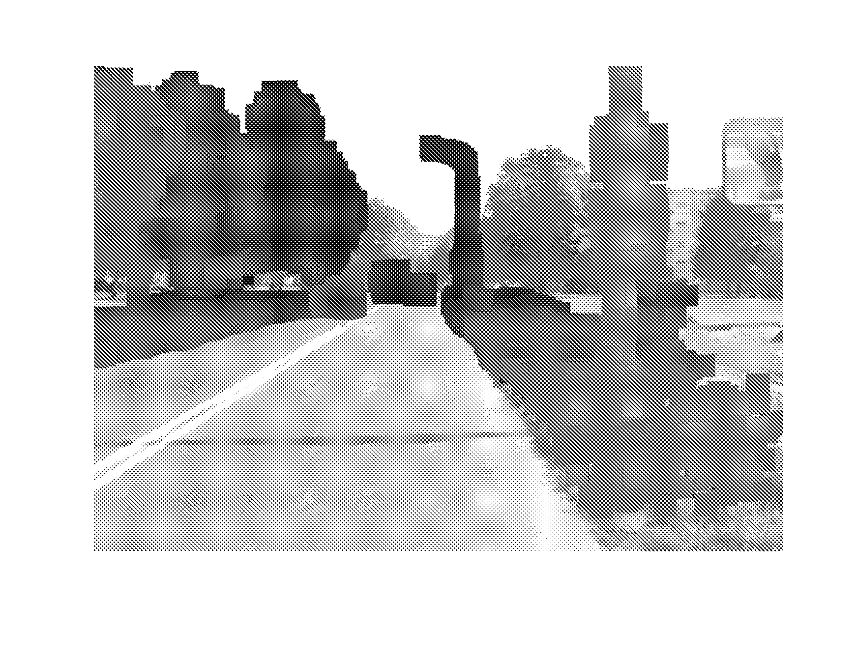
[0062]According to embodiments the scanner data is used to create a mask for masking off areas in the camera data in order to set differential compression parameters within the camera data. So, the scanner data is used to determine regions in the camera data. The regions may be regions of interest, where different regions of interest may have different levels of interest assigned to them. And different compression parameters may be suitable for different levels of interest.

[0063]So, there is provided a method of processing camera data from a mobile mapping system, where the method comprises:

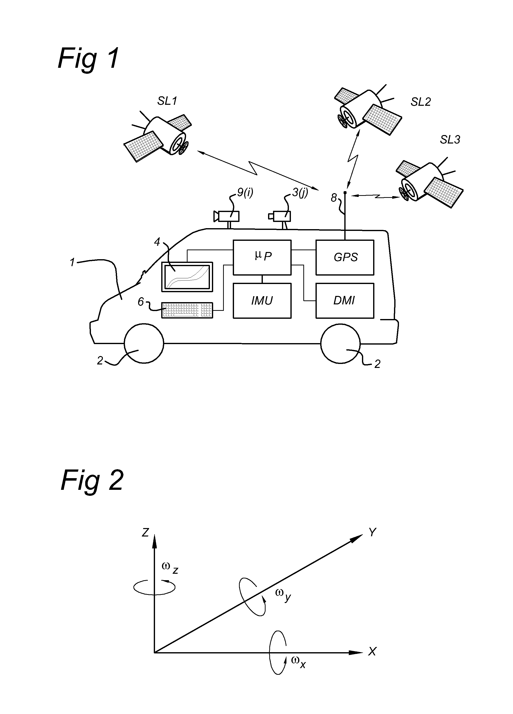
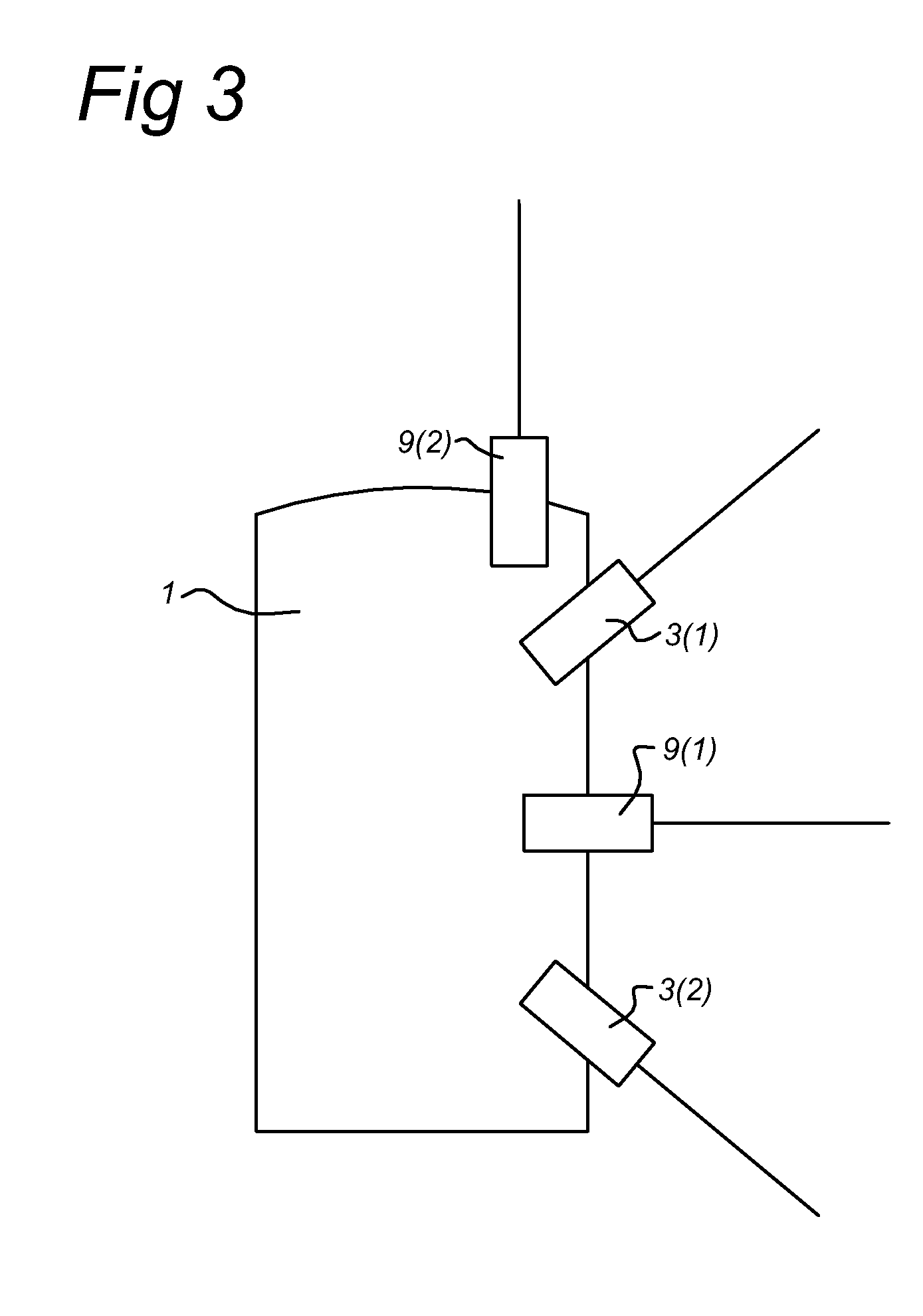
[0064]a) obtaining camera data from at least one camera 9(j) of the mobile mapping system,

[0065]b) detecting at least one region in the camera data,

[0066]c) applying a compression technique on the camera data in a first region,

[0067]wherein the method further comprises obtaining range sensor data from at least a first range sensor 3(1), the range sensor data at least partially corresponding to th...


PUM


Abstract

A method of processing camera data of a mobile mapping system is disclosed. In at least one embodiment, the method includes a) obtaining camera data from at least one camera of the mobile mapping system, b) detecting at least one region in the camera data, c) applying a compression technique on the camera data in a first region, and d) obtaining range sensor data from at least a first range sensor. The range sensor data may at least partially correspond to the camera data. Also, in at least one embodiment, b) includes using the range sensor data to identify the at least one region in the camera data.

Description

FIELD OF THE INVENTION[0001]The present invention relates to a method of processing camera data from a mobile mapping system (MMS), a computer arrangement, a data processing system comprising such a computer arrangement, a computer program product and a data carrier provided with such a computer program product.BACKGROUND OF THE INVENTION[0002]In some MMS applications, the primary intention is to capture pictures of building facades and other fixed objects, like trees, street signs and street lamps that are later used in “real-world” 2D and / or 3D images of streets used in e.g. car navigation systems. Then, these images are shown to drivers of a car provided with such a navigation system such that the driver sees 2D and / or 3D images on a screen of the navigation system corresponding with the real world view when looking through the windows of the car. Such pictures may also be used in other applications than car navigation systems, for instance, in games that can be played on compute...

Claims


Application Information

Patent Timeline
IPC IPC(8): G06K9/00
CPCH04N19/124H04N19/17H04N19/136
Inventor HAGAN, JAMES E.WYSOCKI, ARKADIUSZKMIECIK, MARCIN MICHAL
Owner TOMTOM GLOBAL CONTENT
Learn More