
Clothes dryer

a dryer and cloth technology, applied in the field of cloth dryers, can solve the problems of shortening affecting the service life so as to prolong the lifespan of the supporting roller, prevent stress concentration, and enhance the effect of reliability

Active Publication Date: 2011-02-03
LG ELECTRONICS INC
View PDF10 Cites 5 Cited by
  • Summary
  • Abstract
  • Description
  • Claims
  • Application Information

AI Technical Summary

Benefits of technology

The present invention is a clothes dryer with a roller that supports the drum. The roller is designed to withstand heavy loads and increase the contact area between the roller and the drum to prevent stress concentration. The roller is mounted to a roller shaft using a ball bearing, which makes the roller shaft stronger against heat and abrasion. A stopping portion may be formed at the roller shaft to securely mount the ball bearing. A screw thread may be further formed at one side of the roller shaft for stable mounting of the roller into the clothes dryer. A flat contact portion of the roller may be formed to distribute stress and prolong the lifespan of the roller. The roller frame and outer wheel portion may be stably coupled together using concave-convex portions. The outer wheel portion may be made of rubber with elastic force to enhance the reliability of the clothes dryer. These features make the roller more durable and reliable.

Problems solved by technology

However, when a load supported by the bearing increases, oil included in the oil-less bearing may be discharged out.
This may degrade a lubricating characteristic of the supporting roller 40, and may cause noise occurrence and damage of the supporting roller 40.
Especially, in the case of 24-inch clothes dryer rather than 27-inch clothes dryer, the above problems may become more severe due to a narrow inner space and an overload.
As a result, a stress applied to the supporting roller 40 is concentrated on specific regions, thereby shortening the lifespan of the supporting roller 40.

Method used


Image

  • Clothes dryer
  • Clothes dryer
  • Clothes dryer

Examples


Embodiment Construction

[0029]Description will now be given in detail of the present invention, with reference to the accompanying drawings.

[0030]Hereinafter, a clothes dryer according to the present invention will be explained in more detail with reference to the attached drawings.

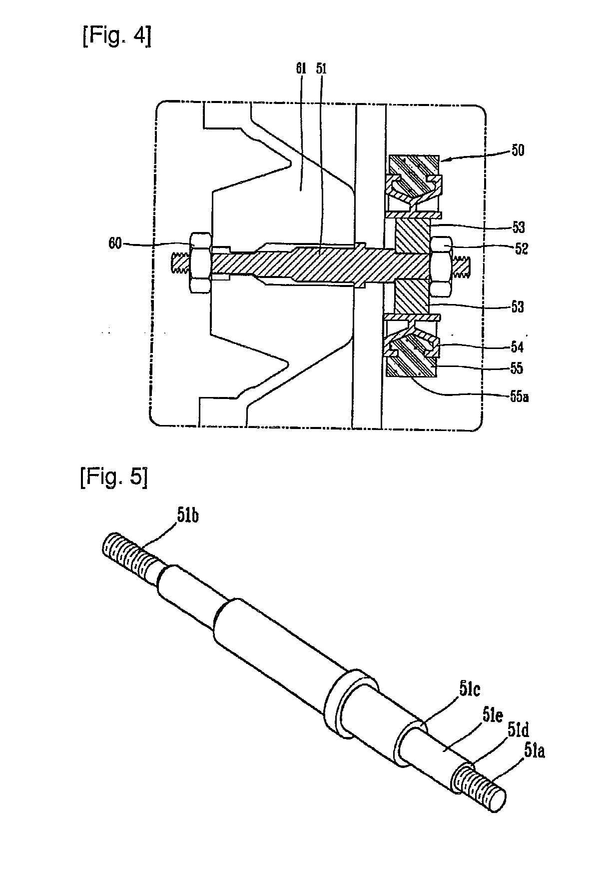
[0031]FIGS. 4 and 5 are views respectively showing a roller for supporting a drum of a clothes dryer according to the present invention.

[0032]The roller for supporting a drum of a clothes dryer according to the present invention is mounted to a roller shaft 51 by a ball bearing 53. That is, in the present invention, the roller is provided with a ball bearing, not the conventional oil-less bearing. This may enable the bearing of the roller shaft 51 to have a stronger endurance against thermal deformation or abrasion due to heat.

[0033]The roller shaft 51 for mounting the roller is provided with a bearing mounting surface 51e for mounting the ball bearing 53. For stable mounting of the ball bearing 53, a stopping portion 51c having...


PUM


Abstract

Disclosed is a clothes dryer comprising a drum rotatably disposed in a body; and a roller disposed below the drum, and configured to support the drum. The roller is mounted to a roller shaft by a ball bearing, and a contact portion of an outer circumferential surface of the roller contacting the drum is formed to be flat.

Description

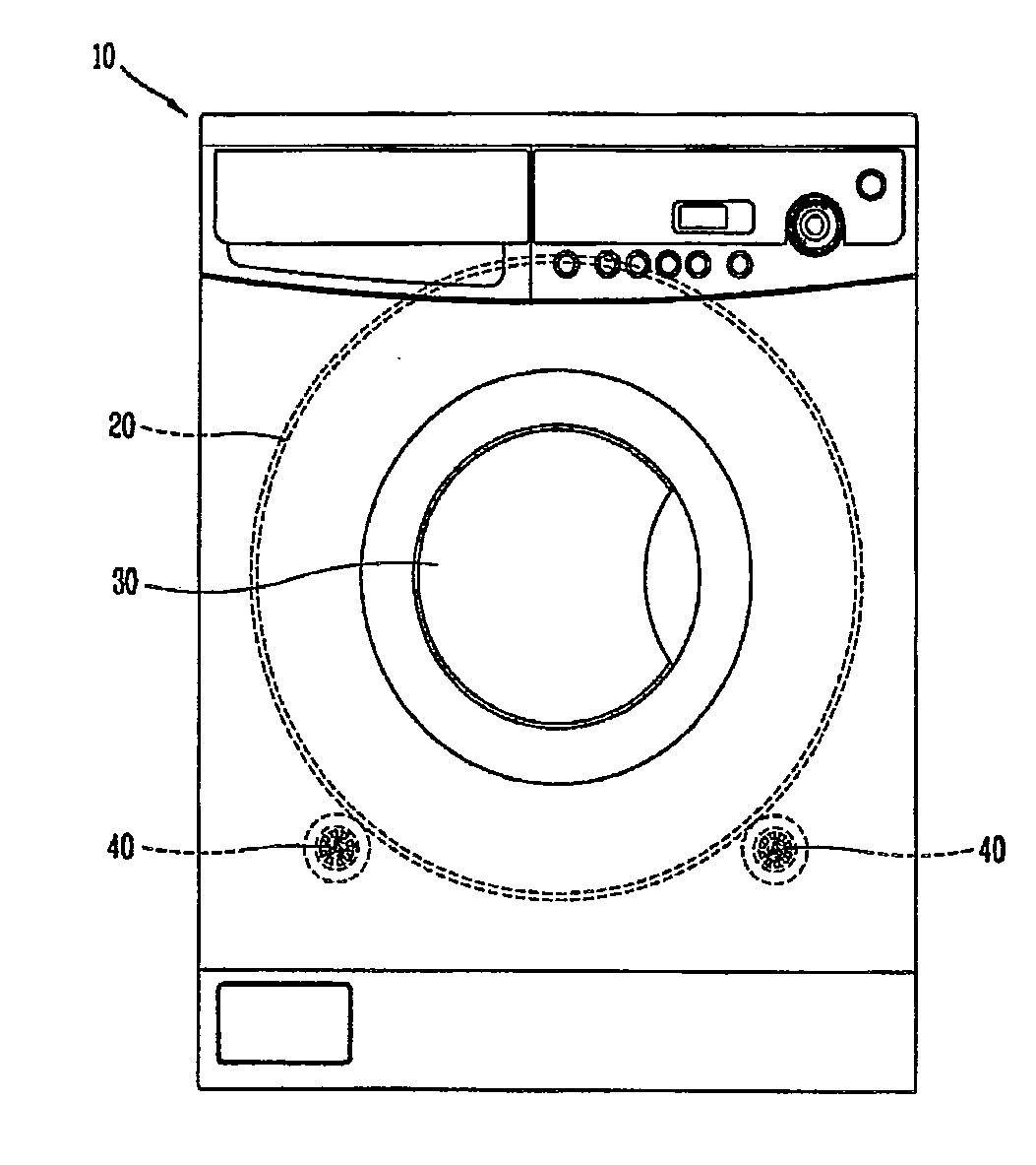
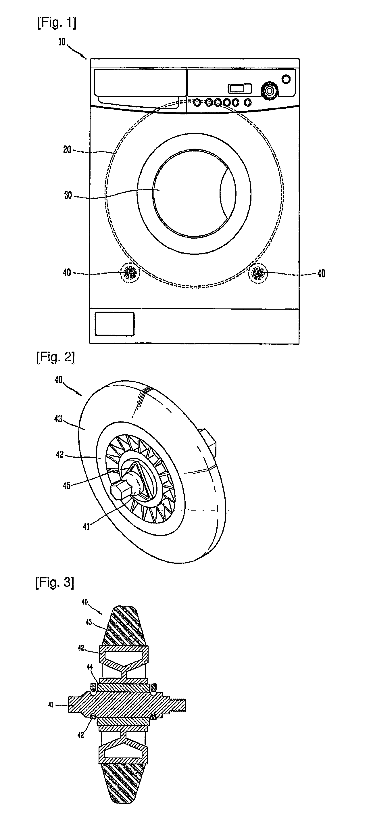
BACKGROUND OF THE INVENTION[0001]1. Field of the Invention[0002]The present invention relates to a clothes dryer, and particularly, to a structure for a roller capable of supporting a drum inside a clothes dryer.[0003]2. Background of the Invention[0004]Recently, a clothes dryer serves to dry an object to be dried by absorbing moisture inside the object by blowing blast generated by an electric heater or a gas heater into a drum. According to a method for processing humid air generated when drying the object, the clothes dryer is largely classified into an exhaustion-type clothes dryer and a condensation-type clothes dryer.[0005]FIG. 1 is a view showing a clothes dryer in accordance with the conventional art.[0006]Referring to FIG. 1, the conventional clothes dryer comprises a body 10 that forms appearance, a drum 20 rotatably installed in the body 10, a door 30 through which an object to be dried is introduced into the clothes dryer, etc. Although not shown, the conventional clothe...

Claims


Application Information

Patent Timeline
Patent Type & Authority Applications(United States)
IPC IPC(8): F26B11/02
CPCD06F58/06D06F58/04D06F58/20
Inventor JUNG, KI-WOOKKIM, MYOUNG-JONG
Owner LG ELECTRONICS INC
Learn More