Zoom lens and imaging apparatus

Inactive Publication Date: 2011-01-27
FUJIFILM CORP
View PDF6 Cites 28 Cited by
  • Summary
  • Abstract
  • Description
  • Claims
  • Application Information

AI Technical Summary

Benefits of technology

[0016] In the zoom lens according to the above-mentioned aspect of the invention, according to the above-mentioned structure, it is easy to prevent a variation in aberration when power varies and obtain a high zoom ratio. In addition, it is easy to reduce the total length of the lens and thus reduce the overall size of the lens.
[0017] When the zoom lens appropriately adopts and satisfies the following preferred structures, it is easy to sufficiently reduce the total length of the lens or sufficiently prevent a variation in aberration when power varies. Therefore, it is easy to improve the performance.
[0030] The imaging apparatus according to the above-mentioned aspect of the invention uses a high-performance zoom lens with a high zoom ratio and a small size as an imaging lens. Therefore, it is possible to reduce the overall size of the imaging apparatus.
[0031] The zoom lens according to the above-mentioned aspect is a five group type in which five lens groups with positive, negative, positive, negative, and positive refractive powers are arranged in this order from the object side. According to the zoom lens, it is easy to obtain a high zoom ratio and it is possible to optimize the structure of each lens group, as compared to a four-group-type zoom lens. Therefore, it is possible to achieve a zoom lens with a high zoom ratio, a small total length, and a small overall size.
[0032] The imaging apparatus according to the above-mentioned aspect uses the high-performance zoom lens with a high zoom ratio and a small size according to the above-mentioned aspect as an imaging lens. Therefore, it is possible to reduce the overall size of the imaging apparatus while maintaining a high imaging performance, such as a high zoom ratio.

Problems solved by technology

Therefore, the total length of the lens increases, which is disadvantageous in reducing the size of the zoom lens.
In this structure, since the fourth lens group includes one lens, there is a large variation in aberration when power varies.
In addition, when the fourth lens group is moved during focusing, there is also a large variation in aberration during focusing.
In addition, the positive lens has strong curvature, and it is necessary to increase the thickness of the positive lens, which is disadvantageous in reducing the size of the zoom lens.
Since the Abbe number is large, this structure is advantageous in correcting longitudinal chromatic aberration, but is disadvantageous in correcting lateral chromatic aberration.
However, in this case, aberration generated from the fourth lens group G4 increases, and it is difficult to effectively correct aberration in the entire power variation range.
If the ratio is more than the upper limit, the refractive power of the fourth lens group G4 is reduced, and it is difficult to reduce the size of the optical system.
However, in this case, aberration generated from the first lens group G1 increases, and it is difficult to effectively correct aberration in the entire power variation range.
In addition, the outside diameter of the first lens group G1 increases, and it is difficult to reduce the size of the optical system.
However, in this case, aberration generated from the third lens group G3 increases, and it is difficult to effectively correct aberration in the entire power variation range.
Therefore, the total length of the lens increases and it is difficult to reduce the size of the optical system.
However, in this case, aberration generated from the fifth lens group G5 increases, and it is difficult to effectively correct aberration in the entire power variation range.
Therefore, the total length of the lens increases, which is disadvantageous in reducing the size of the optical system.
Therefore, total reflection is likely to occur and stray light is likely to be generated.
Therefore, it is difficult to maintain a high zoom ratio.
If the absolute value is less than the lower limit of Condition expression 8, the refractive power of the second lens group G2 is too strong, and it is difficult to sufficiently correct all aberrations.
If the ratio is more than the upper limit, it is difficult to prevent all aberrations due to power variation.

Method used


Image

  • Zoom lens and imaging apparatus
  • Zoom lens and imaging apparatus
  • Zoom lens and imaging apparatus

Examples


numerical examples 2 to 14

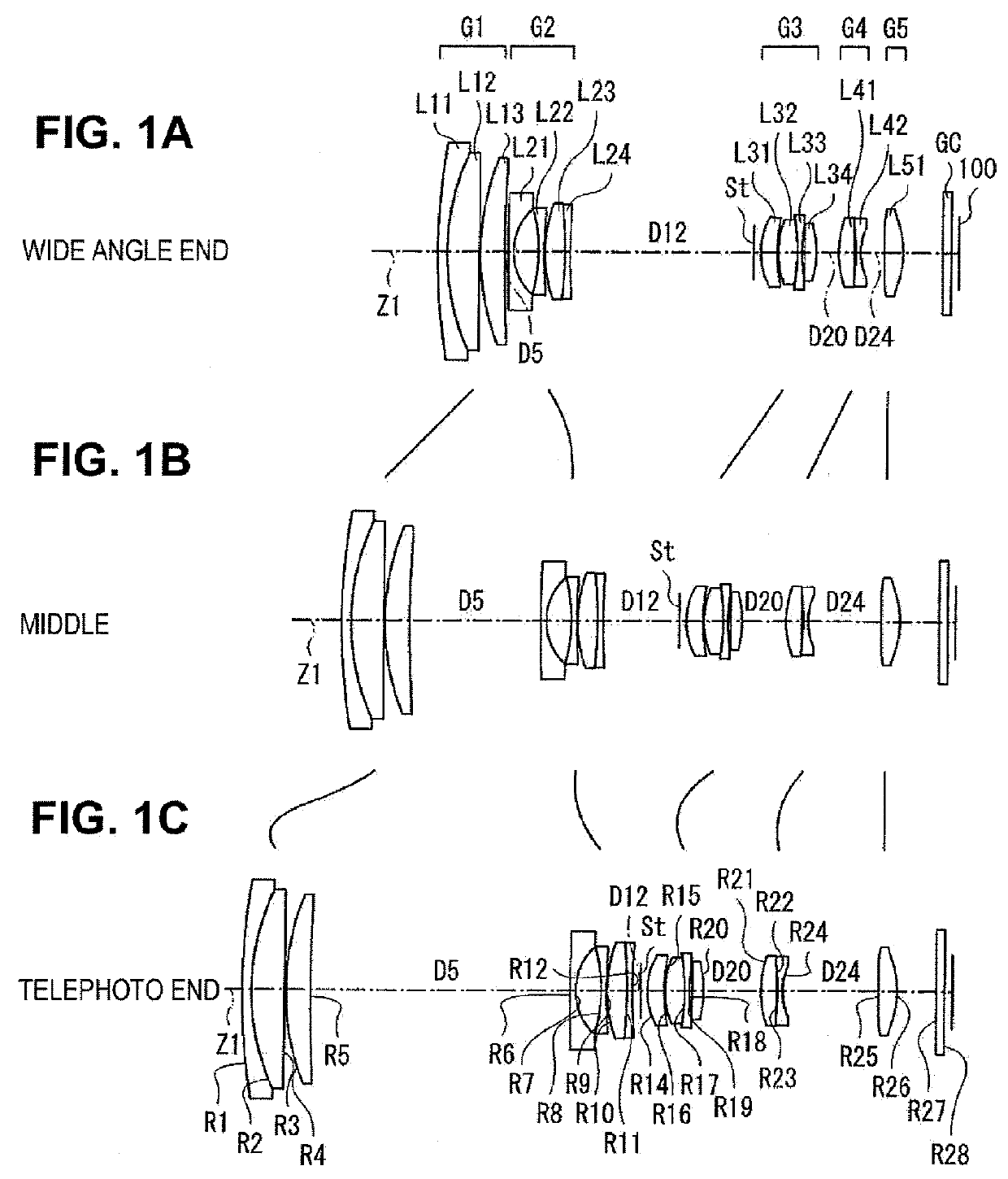
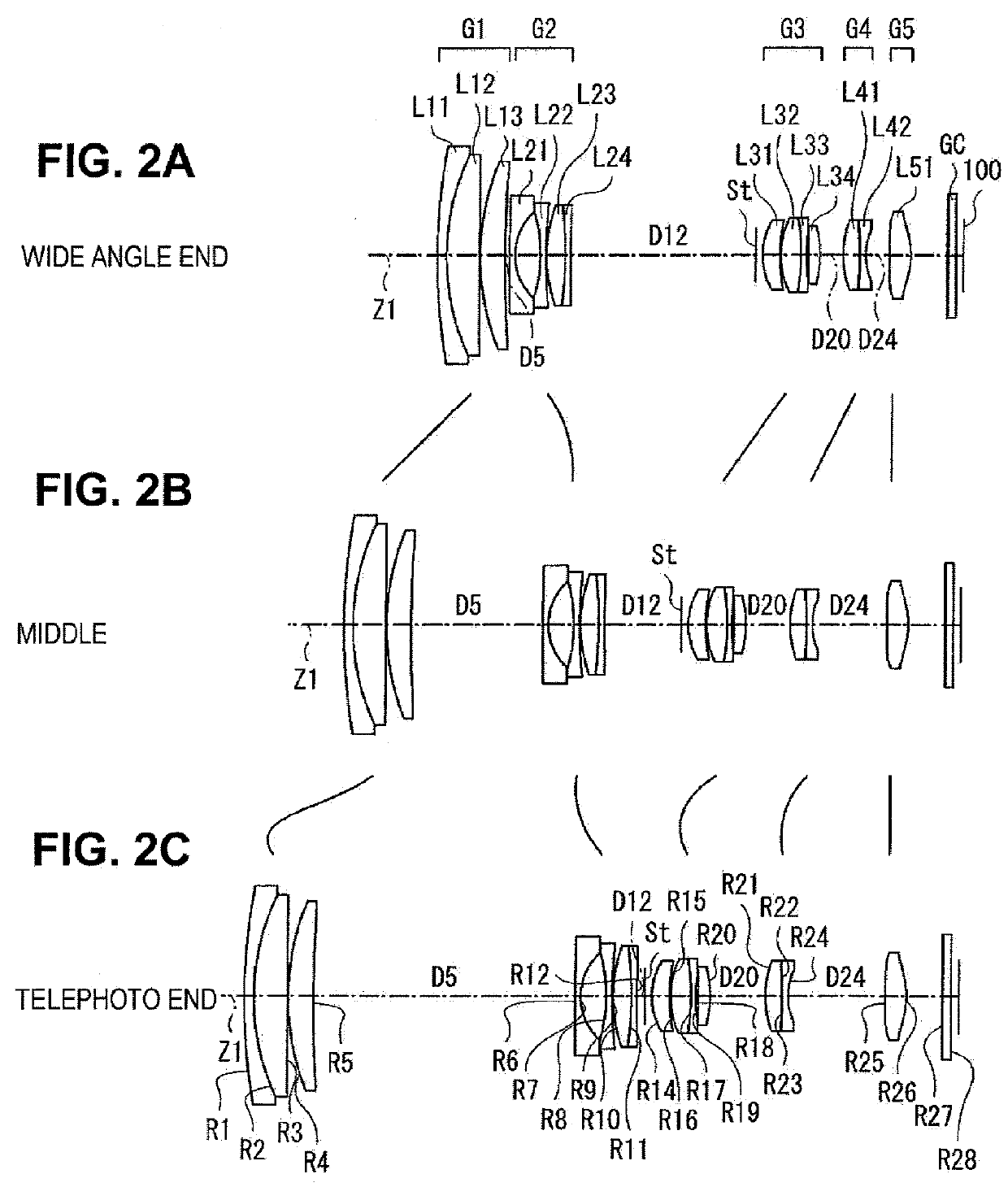
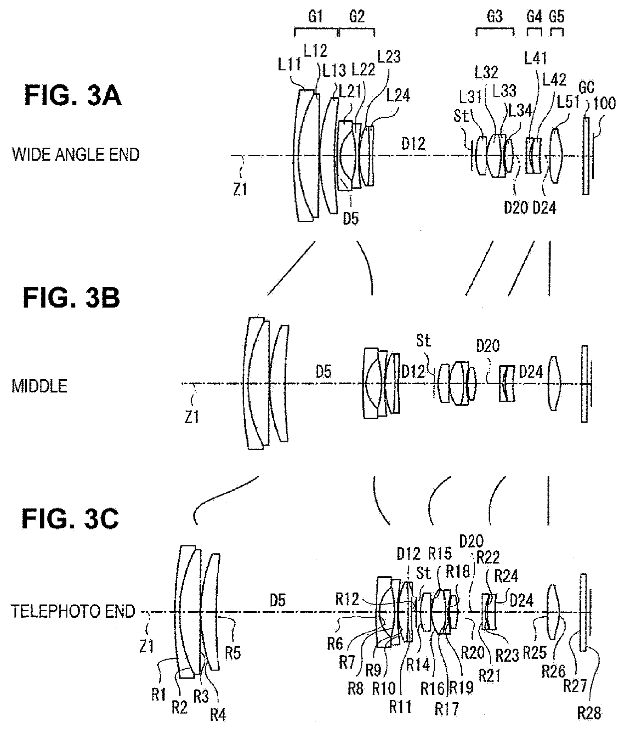
[0144] Similar to Numerical example 1, [Table 4] to [Table 6] show detailed lens data corresponding to the structure of the zoom lens shown in FIGS. 2A, 2B, and 2C as Numerical example 2. Similarly, [Table 7] to [Table 42] show detailed lens data corresponding to the structure of the zoom lenses shown in FIGS. 3A, 3B, and 3C to FIGS. 14A, 14B, and 14C as Numerical examples 3 to 14.

[0145] In the zoom lenses according to Numerical examples 2 to 7 and Numerical example 12, the same surfaces as those in the zoom lens according to Example 1 are aspheric surfaces.

[0146] In the zoom lenses according to Numerical examples 8 to 11, in addition to the lens (lens L35) closest to the image side in the third lens group G3 and the positive lens L51 in the fifth lens group G5, both surfaces of the lens (lens L42) closest to the image side in the fourth lens group G4 are aspheric surfaces.

[0147] In Numerical examples 8 to 11, a cemented surface of the cemented lens includes an adhesive layer. For e...


PUM


Abstract

Disclosed are a zoom lens and an imaging apparatus having a high zoom ratio, a small total length, and a small overall size. A zoom lens includes a first lens group having a positive refractive power, a second lens group having a negative refractive power, a third lens group having a positive refractive power, a fourth lens group having a negative refractive power, and a fifth lens group having a positive refractive power which are arranged in this order from an object side. A gap between the lens groups is changed to change power. The zoom lens satisfies the following Condition expression 1: 0.05<|f4| / ft<0.25   [Condition expression 1] (where ft indicates the focal length of the entire system at a telephoto end and f4 indicates the focal length of the fourth lens group).

Description

[0001] This application is based upon and claims the benefit of priority from the Japanese Patent Application Nos. 2009-172376 filed Jul. 23, 2009, 2010-29324 filed Feb. 12, 2010, and 2010-131096 filed Jun. 8, 2010; the entire contents of which are incorporated herein by reference.[0002] 1. Field of the Invention[0003] The present invention relates to a zoom lens that is appropriately used in, for example, a video camera, a digital still camera, and a portable information terminal (PDA: Personal Digital Assistance) and an imaging apparatus including the same.[0004] 2. Description of the Related Art[0005] In recent years, in an imaging apparatus, such as a digital still camera, with a reduction in the size of an imaging device, such as a CCD (Charge Coupled Device) or a CMOS (Complementary Metal Oxide Semiconductor), there is a demand for reducing the overall size of the apparatus. It is preferable that the total length of the lens be reduced and the overall size of the lens system b...

Claims


Application Information

Patent Timeline
IPC IPC(8): H04N5/262G02B15/14
CPCG02B15/173G02B15/145121
Inventor ORI, TETSUYASUZUKI, TAKASHI
Owner FUJIFILM CORP
Why Eureka
Try Eureka