
Horizontal linear vibrator

a horizontal linear and vibrator technology, applied in mechanical vibration separation, dynamo-electric machines, electrical apparatus, etc., can solve the problems of reducing the lifetime of the vibration generating unit, the disadvantage of the vertical linear vibrator b>10/b> being increased in thickness, and the structure cannot conform to the trend of small and slim cellular phones, etc., to achieve sufficient long life, reduce thickness, and increase vibration strength

Active Publication Date: 2011-01-27
PARTRON
View PDF7 Cites 107 Cited by
  • Summary
  • Abstract
  • Description
  • Claims
  • Application Information

AI Technical Summary

Benefits of technology

[0013]The present invention has been made in an effort to provide a horizontal linear vibrator which can reduce the thickness but increase vibration strength while at the same time guaranteeing a sufficiently long lifetime and satisfactory responsivity.

Problems solved by technology

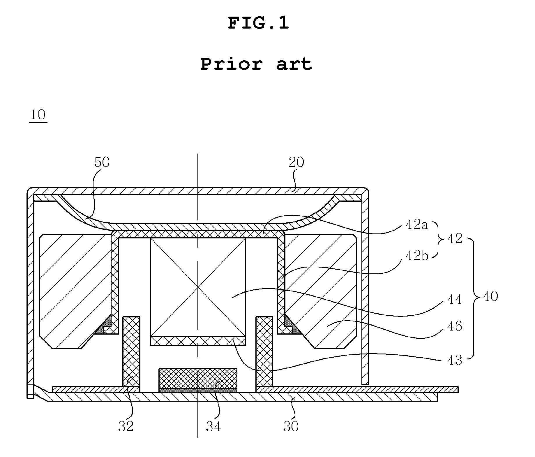
However, in the vibration generating unit having such a structure, when the brush passes through a gap between segments of the commutator, mechanical friction, electric sparks or abrasion is induced, thus creating impurities, such as black powder, thereby to reducing the lifetime of the vibration generating unit.
This induces a disadvantage of the vertical linear vibrator 10 being increased in thickness.
Furthermore, this structure cannot conform to the trend of small and slim cellular phones.

Method used


Image

  • Horizontal linear vibrator
  • Horizontal linear vibrator
  • Horizontal linear vibrator

Examples


Embodiment Construction

[0034]Reference now should be made to the drawings, in which the same reference numerals are used throughout the different drawings to designate the same or similar components. In the following description, when it is determined that the detailed description of the conventional function and conventional structure would confuse the gist of the present invention, such a description may be omitted. Furthermore, the terms and words used in the specification and claims are not necessarily limited to typical or dictionary meanings, but must be understood to indicate concepts selected by the inventor as the best method of illustrating the present invention, and must be interpreted as having meanings and concepts adapted to the scope and sprit of the present invention for understanding the technology of the present invention.

[0035]Hereinafter, an embodiment of the present invention will be described in detail to with reference to the attached drawings.

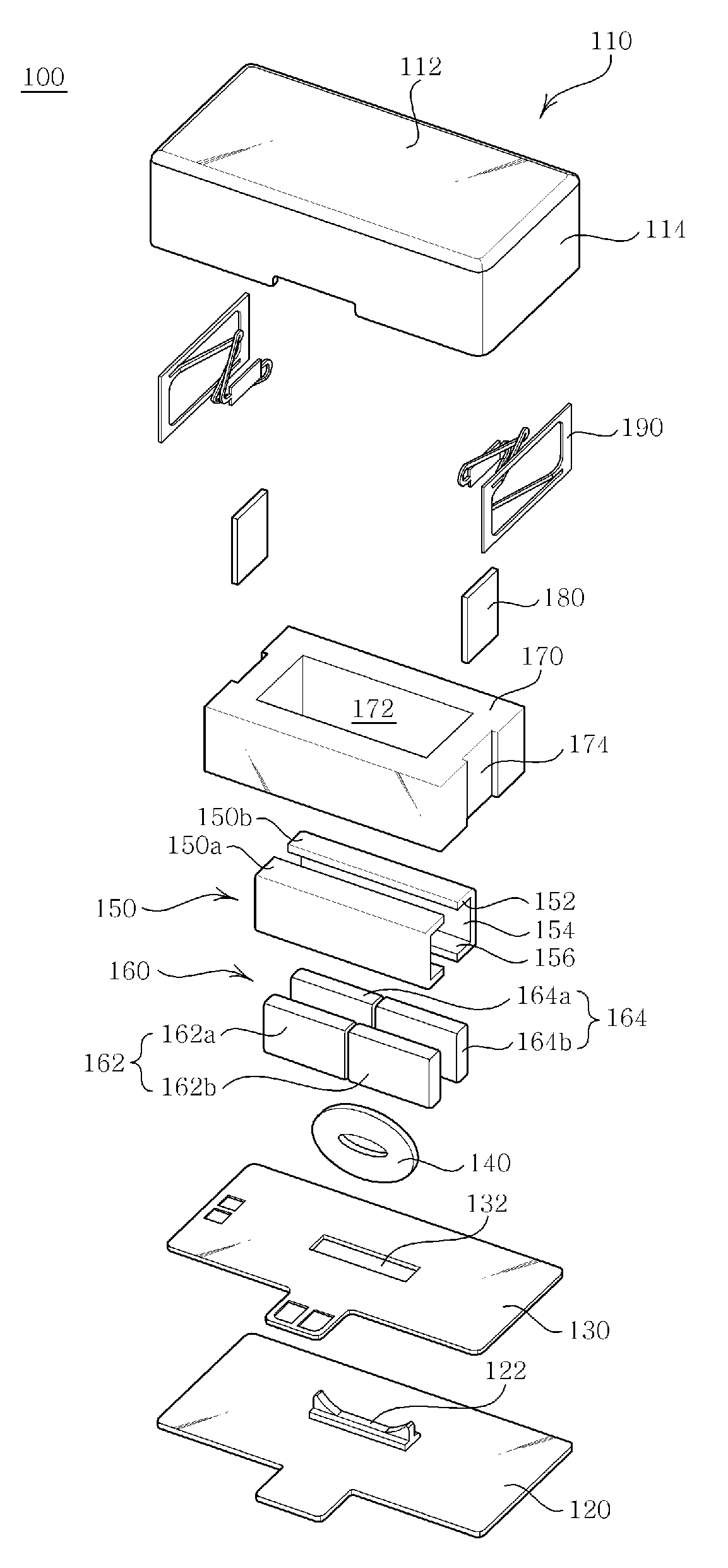
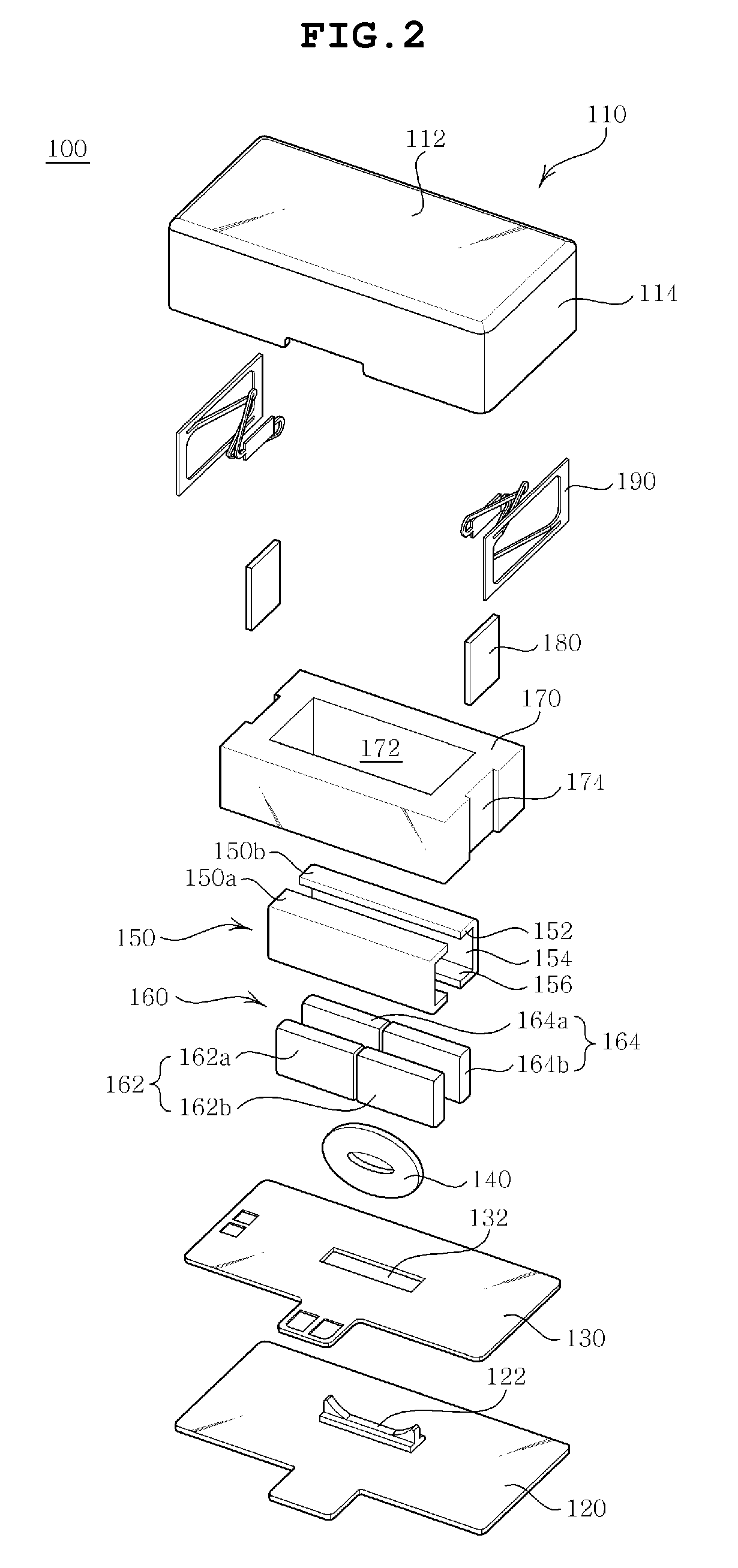
[0036]FIG. 2 is an exploded perspective...


PUM


Abstract

The present invention provides a horizontal linear vibrator which can reduce the thickness but increase the strength of vibrations while at the same time guaranteeing a sufficiently long lifetime and satisfactory responsivity. The horizontal linear vibrator includes a casing, a bracket, a vibration unit, a cylindrical coil and springs. The bracket is coupled to the casing to form an internal space. The vibration unit includes a weight, a pair of yokes and magnets. The weight has an opening therein. The yokes are disposed on the inner surfaces of the weight. The magnets are provided in the yokes such that different poles of the magnets face each other. The cylindrical coil is perpendicularly mounted to the bracket and disposed in space between the pair of yoke. The springs are coupled to both ends of the casing or the bracket. The springs elastically support the vibration unit to allow the vibration unit to vibrate in the horizontal direction.

Description

CROSS REFERENCE TO RELATED APPLICATION[0001]This application claims the benefit of Korean Patent Application No. 10-2009-0066870, filed Jul. 22, 2009, entitled “HORIZONTAL LINEAR VIBRATOR”, which is hereby incorporated by reference in its entirety into this application.BACKGROUND OF THE INVENTION[0002]1. Technical Field[0003]The present invention relates to a horizontal linear vibrator.[0004]2. Description of the Related Art[0005]Generally, portable electronic devices, such as mobile phones, game players, mobile information terminals, etc., have various vibration generating units to prevent noise therefrom from disturbing other people. Particularly, such a vibration generating unit is installed in a cellular phone and used as a mute signal reception indicating unit. Recently, in accordance with the trend to provide a small and slim cellular phone, a reduction in the size and an increase in the function of a vibration generating unit installed in the cellular phone are also required....

Claims


Application Information

Patent Timeline
IPC IPC(8): H02K33/02H02K33/00
CPCH02K33/16B06B1/045H02K33/02H02K35/02
Inventor KIM, YONG JINCHOI, JUN KUNJUN, JAE WOOWOO, KI SUKLEE, KWANG HYUNGBANG, JE HYUNPARK, SEOK JUNLEE, KYUNG HOOH, HWA YOUNG
Owner PARTRON
Learn More