Eureka AIR delivers breakthrough ideas for toughest innovation challenges, trusted by R&D personnel around the world.

Tool path display apparatus for machine tool

Active Publication Date: 2011-01-20
FANUC LTD
View PDF3 Cites 39 Cited by
  • Summary
  • Abstract
  • Description
  • Claims
  • Application Information

AI Technical Summary

Benefits of technology

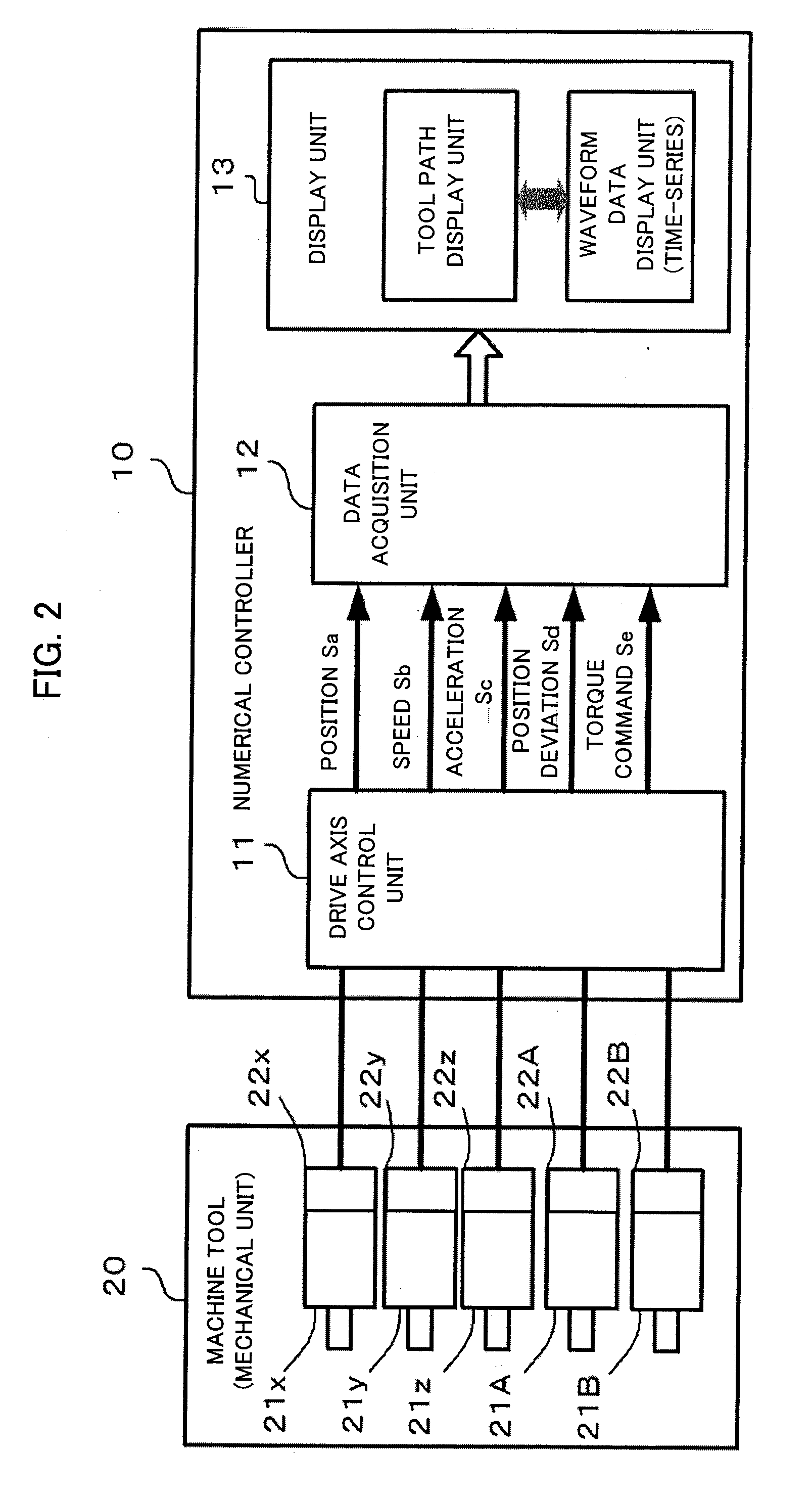
[0019]With the above structure, the tool path display apparatus can intuitively grasp the motion of each axis in response to a point in the tool path and efficiently adjust the motion of each axis. In addition, comparison with each of the thresholds enables the correspondence between the tool path that does not meet the range of the threshold and each of time-series information items to be clearly defined, making the identification of an axis or a point in the tool path with characteristic motion.

Problems solved by technology

A 5-axis machine tool has a rotation axis as a drive axis, so it is difficult to intuitively grasp the correspondence between the motion of each of the drive axes and the motion of the tool tip.
Accordingly, when a particular position on a machined surface is defective, it is difficult to identify the part corresponding to the defective part even by measuring the waveform of each drive axis that is working.

Method used


Image

  • Tool path display apparatus for machine tool
  • Tool path display apparatus for machine tool
  • Tool path display apparatus for machine tool

Examples


first example

Position Deviation of Drive Axes

[0050]FIG. 6 shows the calculation of the coordinates of a tool tip. Although a 5-axis machine tool is configured so that a table is turned with two rotation axes or both a table unit and tool head unit are turned, a machine tool of tool head rotation type shown in FIG. 6 is taken here as an example. In the structure shown in FIG. 6, two rotation axes intersect at right angles in one point. In a more typically structure, the two rotation axes may not intersect, arranged skewed with respect to each other. In this case, if the spatial relation of these two rotation axes is determined, the coordinates of the tool tip can be calculated.

[0051]The 5-axis machine tool which is described below is assumed to have the same machine structure as in FIG. 6, but it should be noted that the present invention is also applicable to a 5-axis machine tool having other machine structures.

[0052]The X-, Y-, and Z-axes are linear axes and the A- and B-axes are rotation axes...

second example

Torque Command

[0056]In the display processing in FIG. 7, the torque command Se can also be used instead of the position deviation Sd. In this case, it is sufficient to change the above algorithm so that the torque command is obtained instead of the position deviation in step SS100, the torque command obtained in step SS100 is displayed as the waveform of time-series data in step SS102, and the torque command obtained in step SS102 is compared with a preset threshold for comparison of torque commands in step SS103.

third example

Position Deviation of Rotation Axes (Second Position Deviation)

[0057]FIG. 8 describes the calculation of a position deviation (second position deviation) in case where the second position deviation is compared with a threshold in display processing.

[0058]If the position deviation (angle deviation) of the A-axis is assumed to be Δa, the second position deviation of the A-axis is represented by L×Δa, where L is a tool length (a constant value) which equals to the distance between the rotation axis of the A-axis and the tool tip. If the position deviation (angle deviation) of the B-axis is assumed to be Δb, the distance between the rotation axis of the B-axis and the tool tip equals L×cos(a(t)), which depends on the position of the A-axis. Accordingly, the second position deviation of the B-axis equals L×cos(a(t))×Δb.

[0059]The second position deviation can be calculated similarly in the table rotation type machine structure in FIG. 9. Here, it is assumed that one rotation axis that ch...


PUM


Abstract

First and second screens are set for a tool path display apparatus for displaying a path of the tip of a tool attached to a machine tool. The first screen displays the three-dimensional path of the tip of the tool obtained by synthesizing the position information of the drive axes of a 5-axis machine tool. The second screen displays the waveforms of the position deviations and current instructions of the drive axes in chronological order. When a part (line segment) of the three-dimensional path of the tip of the tool is selected on the first screen, the display attribute of the corresponding time area is changed on the second screen so that the time area can be identified.

Description

BACKGROUND OF THE INVENTION[0001]1. Field of the Invention[0002]The present invention relates to a tool path display apparatus for machine tools and, more particularly, to a display apparatus capable of visually grasping the correspondence between the position of a tool tip in a three-dimensional path and the position in a time axis of time-series waveform data for each of axes.[0003]2. Description of the Related Art[0004]Some currently-used numerical controllers for controlling machine tools have a function of displaying a specified path or a function of displaying the path in which the tool actually moved.[0005]Japanese Patent Application Laid-Open No. 7-5908 discloses a measuring / monitoring apparatus that obtains a position signal etc. from appropriate points in a controller controlling the position and speed for machine operation. The measuring / monitoring apparatus creates time-series data by sampling the obtained signals at specified intervals, graphically displays a motion pat...

Claims


Application Information

Patent Timeline
IPC IPC(8): G06F19/00G01L3/00G01P15/00
CPCG05B2219/35349G05B19/409
Inventor OKITA, TADASHIKAWAMURA, HIROYUKITEZUKA, JUNICHISUGIYAMA, KAZUYUKI
Owner FANUC LTD
Why Eureka
Eureka Blog
Learn More