
Anatomically Approximate Prosthetic Mitral Valve

a prosthetic and mitral valve technology, applied in the field of medical devices, can solve the problems of reducing the amount of oxygen supplied to the body, deteriorating quickly, and complex manufacturing process of tissue heart valves, and achieve the effect of reducing the overall height profile of the valve and increasing the area of the orifice valv

Active Publication Date: 2011-01-20
EDWARDS LIFESCIENCES CORP
View PDF26 Cites 171 Cited by
  • Summary
  • Abstract
  • Description
  • Claims
  • Application Information

AI Technical Summary

Benefits of technology

The design enhances durability and blood flow by simulating the natural mitral valve anatomy, reducing stress on the valve components and allowing for a lower outflow profile, enabling intra-atrial implantation without injuring the left ventricle.

Problems solved by technology

Unfortunately, some proposed valves deteriorate quickly, and some inordinately restrict flow which undesirably reduces the amount of oxygen supplied to the body.
The manufacturing process of tissue heart valves is very mature and complex from the quality control point of view, and only minimal improvements in valve durability have been achieved in recent years.

Method used


Image

  • Anatomically Approximate Prosthetic Mitral Valve
  • Anatomically Approximate Prosthetic Mitral Valve
  • Anatomically Approximate Prosthetic Mitral Valve

Examples


Embodiment Construction

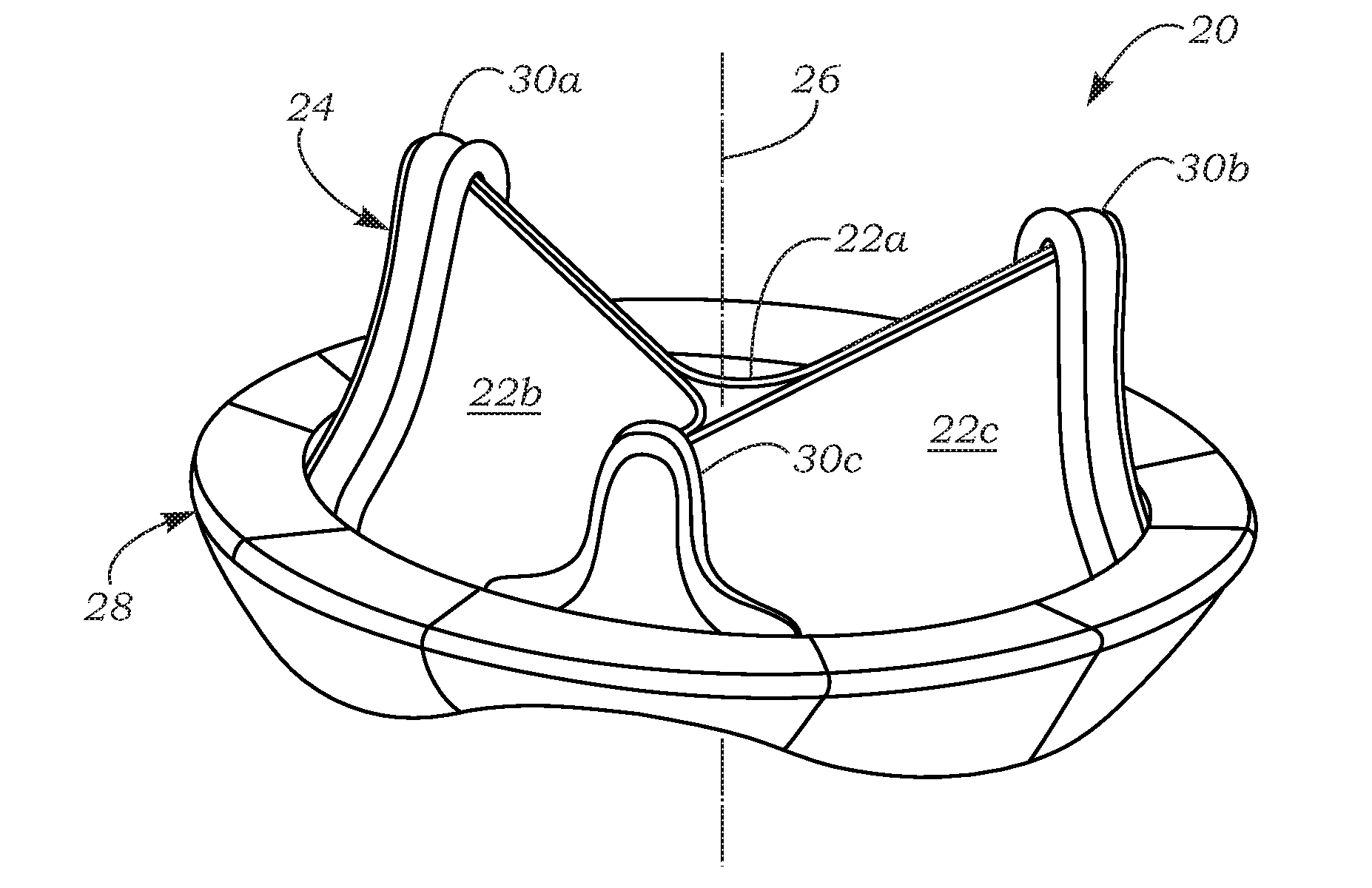
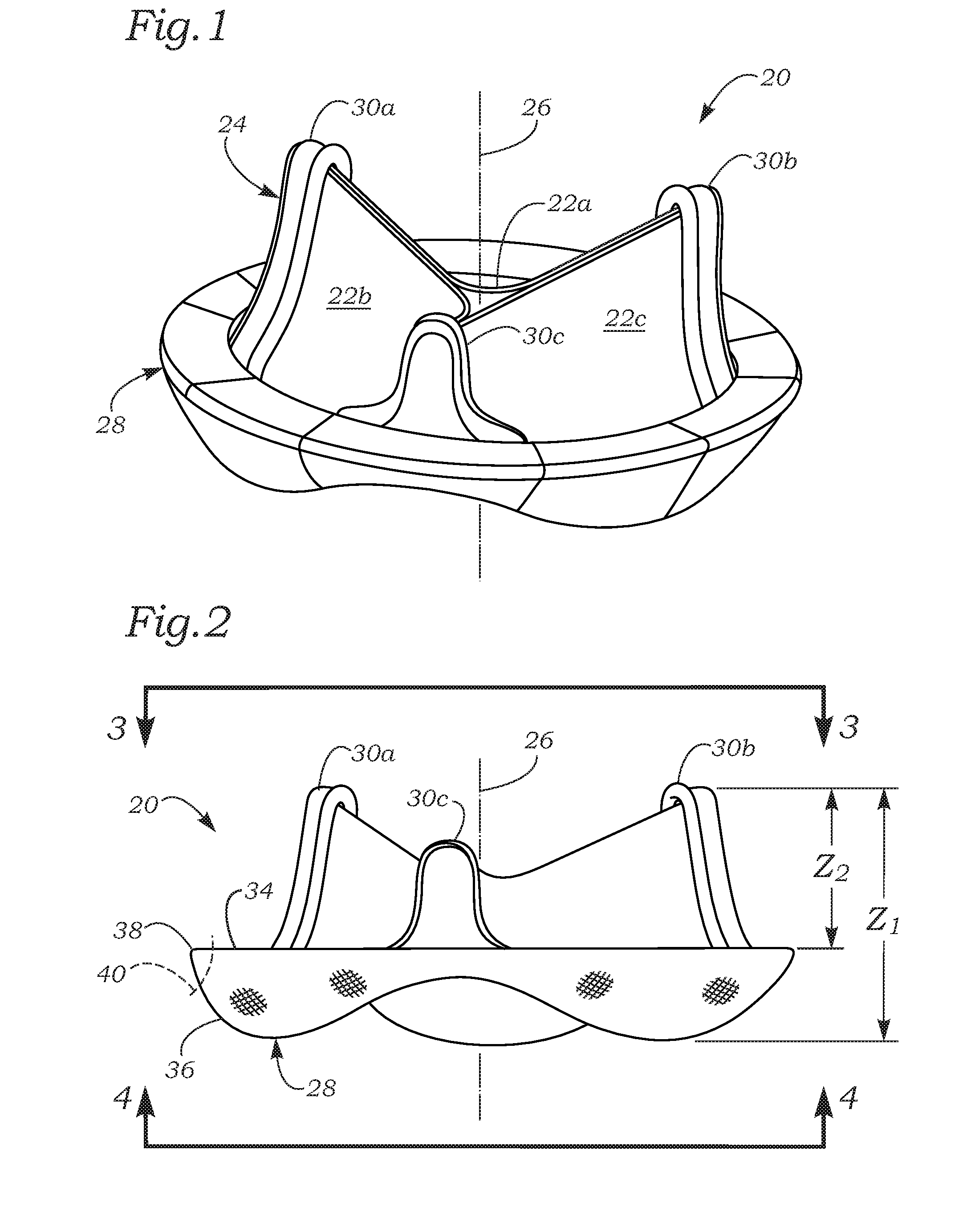
[0028]The present invention pertains to prosthetic heart valves that simulate the natural human heart valve anatomy, in particular for the mitral valve. For instance, the shape of the flow orifice is non-circular so as to mimic the shape of the mitral annulus in the systolic phase. Also, in a preferred embodiment three leaflets are utilized with at least one being substantially different than the other two. The reader will see from the following description and appended drawings various features of the exemplary valves that are intended to mimic the natural mitral valve. However, because of the nature of prosthetic heart valves in terms of durability and implantation requirements, a prosthetic valve cannot precisely mirror a natural valve. Accordingly, the prosthetic mitral valve disclosed herein is termed “anatomically approximate” to indicate one or more modifications from conventional prosthetic valves that render it more like a natural valve. It should be noted that one or more ...


PUM


Abstract

An anatomically approximate prosthetic heart valve includes dissimilar flexible leaflets, dissimilar commissures and / or a non-circular flow orifice. The heart valve may be implanted in the mitral position and have one larger leaflet oriented along the anterior aspect so as to mimic the natural anterior leaflet. Two other smaller leaflets extend around the posterior aspect of the valve. A basic structure providing peripheral support for the leaflets includes two taller commissures on both sides of the larger leaflet, with a third, smaller commissure between the other two leaflets. The larger leaflet may be thicker and / or stronger than the other two leaflets. The base structure defines a flow orifice intended to simulate the shape of the mitral annulus during the systolic phase. For example, the flow orifice may be elliptical. A relatively wide sewing ring has a contoured inflow end and is attached to the base structure in such a way that the valve can be implanted in an intra-atrial position and the taller commissures do not extend too far into the left ventricle, therefore avoiding injury to the ventricle.

Description

CROSS REFERENCE TO A RELATED PATENT APPLICATION[0001]The present application is a continuation of U.S. patent application Ser. No. 11 / 039,522 filed on Jan. 19, 2005, which claims priority under 35 U.S.C. §119(e) to U.S. Provisional Patent Application No. 60 / 538,516, filed on Jan. 23, 2004, the disclosures of which are hereby incorporated by reference in their entireties.FIELD OF THE INVENTION[0002]The present invention relates generally to medical devices, and more particularly to a prosthetic mitral heart valve having an asymmetric periphery and unequal leaflets.BACKGROUND OF THE INVENTION[0003]Two primary types of heart valve replacements or prostheses are known. One is a mechanical-type heart valve that uses a ball and cage arrangement or a pivoting mechanical closure supported by a base structure to provide unidirectional blood flow, such as shown in U.S. Pat. No. 4,306,319 to Kaster. The other is a tissue-type or “bioprosthetic” valve having flexible leaflets supported by a bas...

Claims


Application Information

Patent Timeline
Patent Type & Authority Applications(United States)
IPC IPC(8): A61F2/24A61F2/00
CPCA61F2/2409A61F2/2412A61F2230/0076A61F2/24A61F2230/0095A61F2/2418A61F2230/0008A61F2230/0069A61F2/2403A61F2/2448
Inventor CARPENTIER, ALAIN F.LAM, HUNG L.
Owner EDWARDS LIFESCIENCES CORP
Learn More