
Moving image recording method and apparatus, and moving image coding method and moving image coder

a technology of moving image and recording method, which is applied in the field of moving image recording method and apparatus, and moving image coding method and moving image coder, which can solve the problems of low accuracy of parallax information of a b frame and p frame, low quality of three-dimensional view, and excessive complexity of operation, etc., and achieves high quality

Inactive Publication Date: 2011-01-20
FUJIFILM CORP
View PDF7 Cites 14 Cited by
  • Summary
  • Abstract
  • Description
  • Claims
  • Application Information

AI Technical Summary

Benefits of technology

[0008]In view of the foregoing problems, an object of the present invention is to provide a moving image recording method and apparatus in which right and left eye images retrieved in forms of moving images can be processed with high quality to obtain a video stream, and moving image coding method and moving image coder.
[0024]Consequently, right and left eye images retrieved in forms of moving images can be processed with high quality to obtain a video stream, because parallax information is considered and recorded together within the moving image file.

Problems solved by technology

However, there is a drawback in that distortion due to the compression is conspicuous typically in the still image display of three B frame and P frame in the moving image, so that quality of the three dimensional view will be low.
Additional processing for the parallax information will complicate the operation excessively.
Also, a problem arises in low correctness in the parallax information of a B frame and P frame.

Method used


Image

  • Moving image recording method and apparatus, and moving image coding method and moving image coder
  • Moving image recording method and apparatus, and moving image coding method and moving image coder
  • Moving image recording method and apparatus, and moving image coding method and moving image coder

Examples


Embodiment Construction

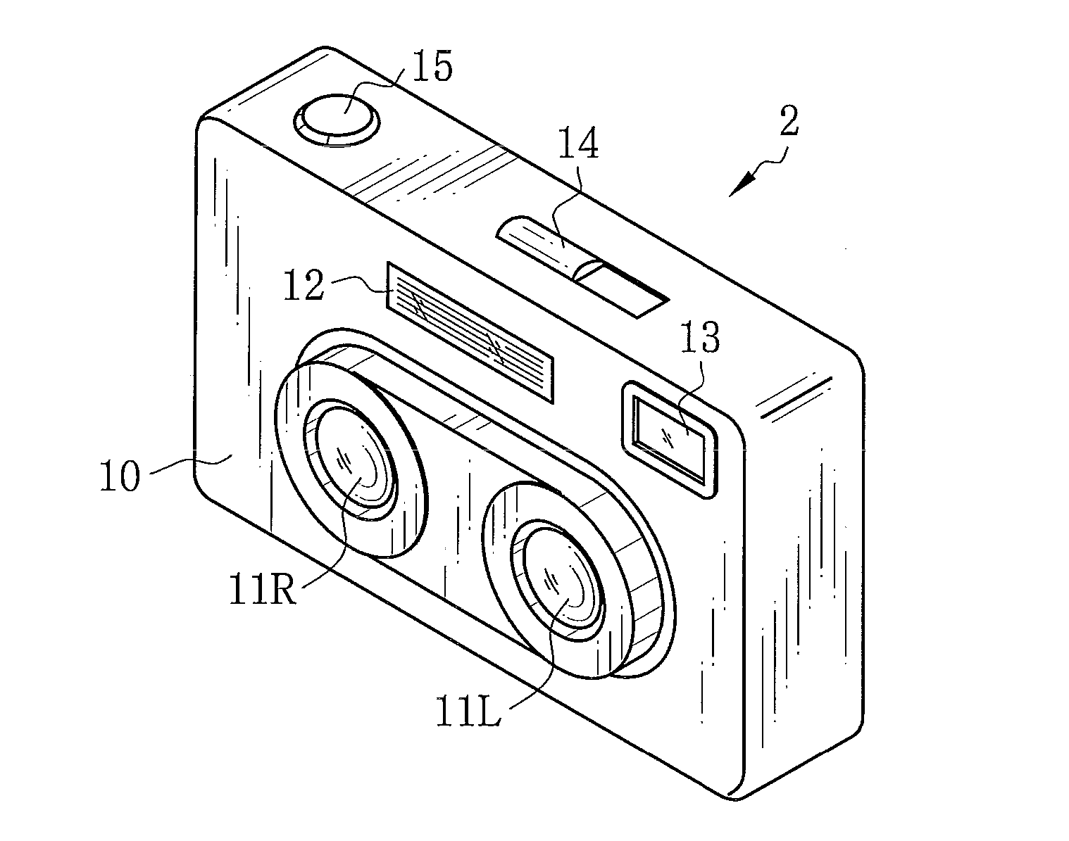
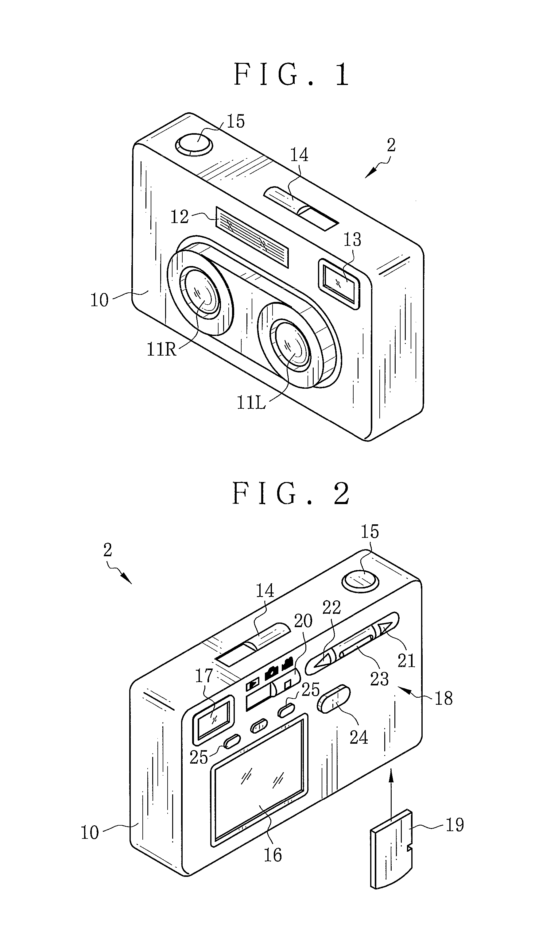
[0038]In FIGS. 1 and 2, a three dimensional camera 2 includes a camera body 10 of a box shape, and is an instrument for photographing an object at two view points to form a three dimensional image. Elements disposed on a front surface of the camera body 10 include lens systems 11L and 11R, a flash light source 12 and an objective window 13 of a viewfinder.

[0039]Each of the lens systems 11L and 11R includes a plurality of lenses / lens groups, such as a main lens, magnification lens, focusing lens and the like. The lens systems 11L and 11R are symmetric with each other with respect to the center of the front surface of the camera body 10. A base line length of the camera body 10 is an interval between the lens systems 11L and 11R in the longitudinal direction, and is specifically 60 mm. A convergence angle defined between optical axes of the lens systems 11L and 11R is 1.5 degrees.

[0040]A power switch 14 and a release button 15 are disposed on an upper surface of the camera body 10. Th...


PUM


Abstract

A moving image recording apparatus for a moving image file of a three dimensional moving image is provided, and includes a parallax detection device for determining parallax information of parallax of one principal object commonly present in images of an image set from multiple view points among image sets of a stream for the three dimensional moving image. A compressor compresses the images in still image compression coding for separately coding the images in the three dimensional moving image, to obtain compressed image data. A recording control unit records in a storage medium the moving image file constituted by plural blocks each of which includes the compressed image data of the image set and the parallax information from the parallax detection device. Preferably, the object is a face region of a person. The still image compression coding is JPEG coding.

Description

BACKGROUND OF THE INVENTION[0001]1. Field of the Invention[0002]The present invention relates to a moving image recording method and apparatus, and moving image coding method and moving image coder. More particularly, the present invention relates to a moving image recording method and apparatus in which right and left eye images retrieved in forms of moving images can be processed with high quality to obtain a video stream, and moving image coding method and moving image coder.[0003]2. Description Related to the Prior Art[0004]A moving image of a three dimensional view is produced by processing right and left eye images photographed at two view points in a three dimensional camera. To this end, various recording methods are known. U.S. Pat. Nos. 5,767,898 and 6,075,556 (corresponding to JP-A 8-070475) discloses synthesis of right and left eye images alternately per one scan in a horizontal direction. A synthesized moving image is compressed by coding of the MPEG format. Also, U.S. ...

Claims


Application Information

Patent Timeline
Patent Type & Authority Applications(United States)
IPC IPC(8): H04N13/00G06T19/00H04N5/92H04N13/239H04N19/00H04N19/597
CPCH04N13/0055H04N19/597H04N13/0239H04N13/189H04N13/239
Inventor WATANABE, MIKIONAKAMURA, SATOSHI
Owner FUJIFILM CORP
Learn More