
Ladder stabilisation and safety system

Inactive Publication Date: 2011-01-20
SHEFFIELD LANCE RODNEY
View PDF10 Cites 53 Cited by
  • Summary
  • Abstract
  • Description
  • Claims
  • Application Information

AI Technical Summary

Benefits of technology

[0038]Whilst the simplest arrangement for engaging and disengaging the pawl is a pivot pin, the function of this first aspect of the invention is to ensure that the compressive force transmitted from the inner member via the ratchet means to the outer member, is not substantially borne by the pivot pin but by a shoulder and load transfer means. This may be assisted by slight ovality or irregularity of the pivot pin in relation to the bearing surface in which the pin rotates. During load bearing the pivot pin only holds the ratchet means in the horizontal plane thus preventing leverage forces developing on the pin which might have a tendency to disengage the ratchet teeth. Wear on the pin can be substantially attenuated and a relatively inexpensive material, and production method thereof, can be employed in the ratchet means. As load taken by the pivot is reduced the housing or holding component connecting the pawl device to the outer member may also be of moulded plastic.
[0171]To keep down overall length of the sections while still providing reasonable levelling capability one may modify the connection so that its projection in the dismantled condition is reduced.

Problems solved by technology

This takes time and is liable to be neglected.
Often a ladder user will think the ladder safe, use it without the safety equipment and then have an accident, resulting in serious injury or even death.
The problems with all these devices are that solutions in one plane cause problems in others.
There is no stability and safety equipment that can cover all the ways ladders are now being used and that will allow simple storage and transportation.
However, because any ladder stabilising device will require to be strong, to have a long life, and to be substantially incapable of failure, the cost thereof risks being wholly disproportionate to that of the ladder.
The number of ladder types already in existence is huge.

Method used


Image

  • Ladder stabilisation and safety system
  • Ladder stabilisation and safety system
  • Ladder stabilisation and safety system

Examples


Embodiment Construction

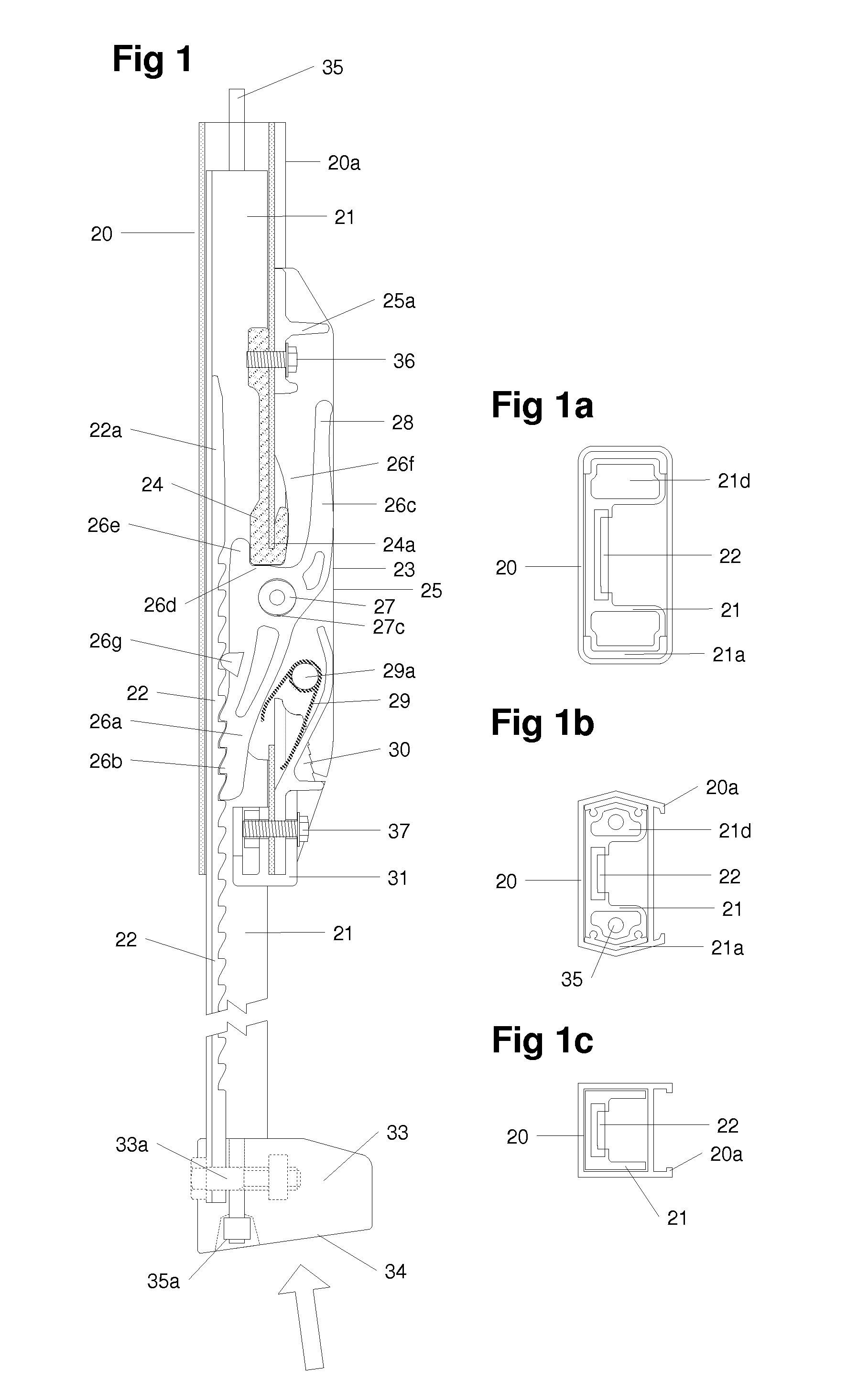
[0222]FIG. 1 show the vertical cross section of the general arrangement of a telescopic extending device.

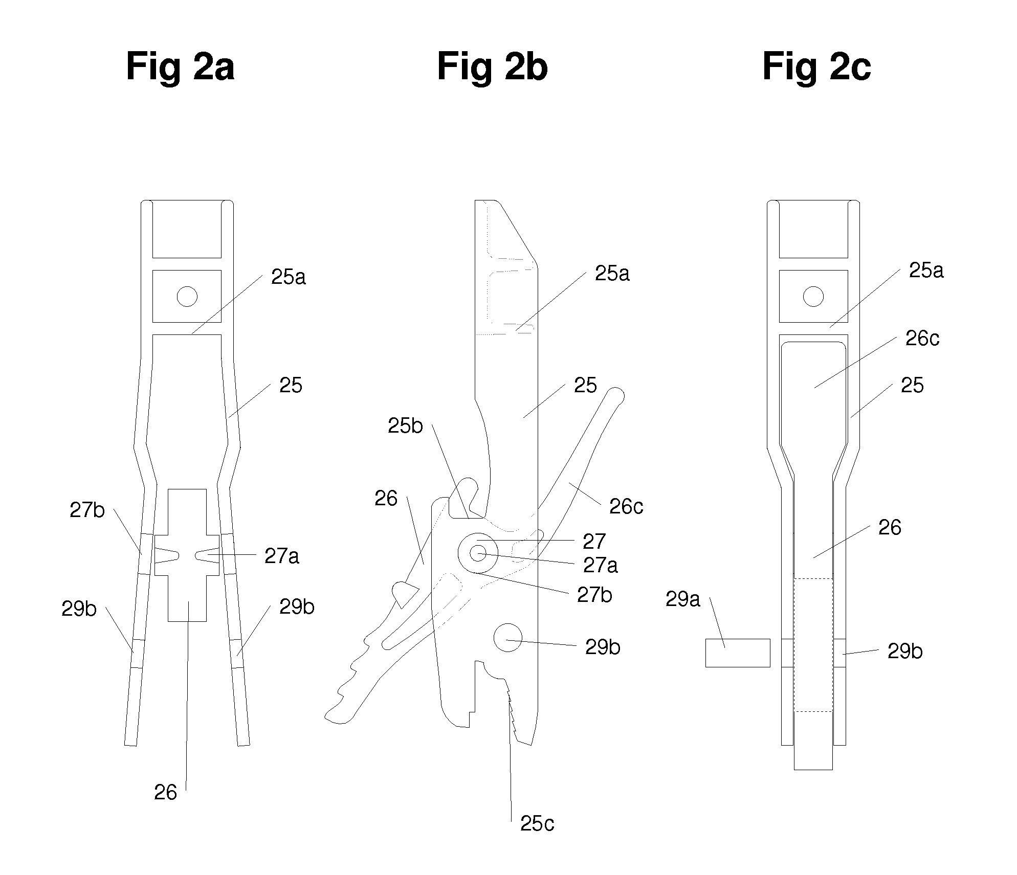
[0223]The device consists of an outer member 20 that can continue upwards beyond the diagram, an inner or extending member 21 that moves vertically in relationship to the outer member 20. Attached to the member 21 is a rack of ratchet teeth 22. The up and downward movement of the member 21 is controlled by a pawl assembly 23, which comprises a load transfer element 24, a housing assembly 25, a pawl 26 comprising a pawl arm 26a, a plurality of ratchet teeth 26b, an operating lever 26c a pawl shoulder 26d, a projection 26e and a pivot pin 27. The rotation of the pawl 26 about the pin 27 in use is limited to around 7 degrees; during installation of assembly the rotation movement is greater.

[0224]The operating lever 26c is arranged for pressing by the user to separate the ratchet teeth and is situated outside the member 20. The pawl shoulder 26d transmits loads from the member 21 via...


PUM

PropertyMeasurementUnit
Lengthaaaaaaaaaa
Frictionaaaaaaaaaa

Abstract

Expandable load bearing device for use on a ladder and comprising an outer member (20), an inner member (21) movable within the outer member, and ratchet means having a pawl (26) attachable to the outer member and a rack (22) attachable to the inner member, the pawl being movable into and out of engagement with the rack to prevent the movement of the inner member towards the outer member, and the pawl having a shoulder (36d) arranged to bear upon a load transfer member (24) on the outer member when the pawl is in engagement with the rack.

Description

FIELD OF THE INVENTION [0001]This Patent Specification relates to a stability (stabilisation) and safety system that can be incorporating a to wide range of ladders, step ladders and access equipment and in concern to make the equipment far safer and easier to use than previously possible.BACKGROUND OF THE INVENTION [0002]Ladder levelling and stabilising equipments available on the market at present are generally add on devices that are stored or transported separately from the ladder and thus require additional operations to collect and set them up for use. This takes time and is liable to be neglected. Often a ladder user will think the ladder safe, use it without the safety equipment and then have an accident, resulting in serious injury or even death.[0003]Certain manufacturers are at last providing equipment attached to ladders; these include stabiliser bars between the two stiles at ground level extending sideways, levelling devices almost along the same lines with other manuf...

Claims


Application Information

Patent Timeline
IPC IPC(8): G05G5/06F16M11/26E06C7/06E04G1/22E06C1/22E06C1/12B23P11/00
CPCE04G1/24E06C1/12E06C1/22E06C1/39Y10T29/49826E06C7/44F16B7/105Y10T74/20684E06C7/423E04G2001/248
Inventor SHEFFIELD, LANCE RODNEY
Owner SHEFFIELD LANCE RODNEY
Learn More