Elastic sheet structure

a technology of elastic sheets and conductive connections, applied in the direction of soldering/welded conductive connections, printed circuits, electrical devices, etc., can solve the problem of difficult replacement if needed

Inactive Publication Date: 2011-01-13
CHI MEI COMM SYST INC
View PDF12 Cites 4 Cited by
  • Summary
  • Abstract
  • Description
  • Claims
  • Application Information

AI Technical Summary

Problems solved by technology

However, the elastic sheet structures are welded to the electronic components or circuit boards, and accordingly are difficult to replace if needed.

Method used


Image

  • Elastic sheet structure
  • Elastic sheet structure
  • Elastic sheet structure

Examples


Embodiment Construction

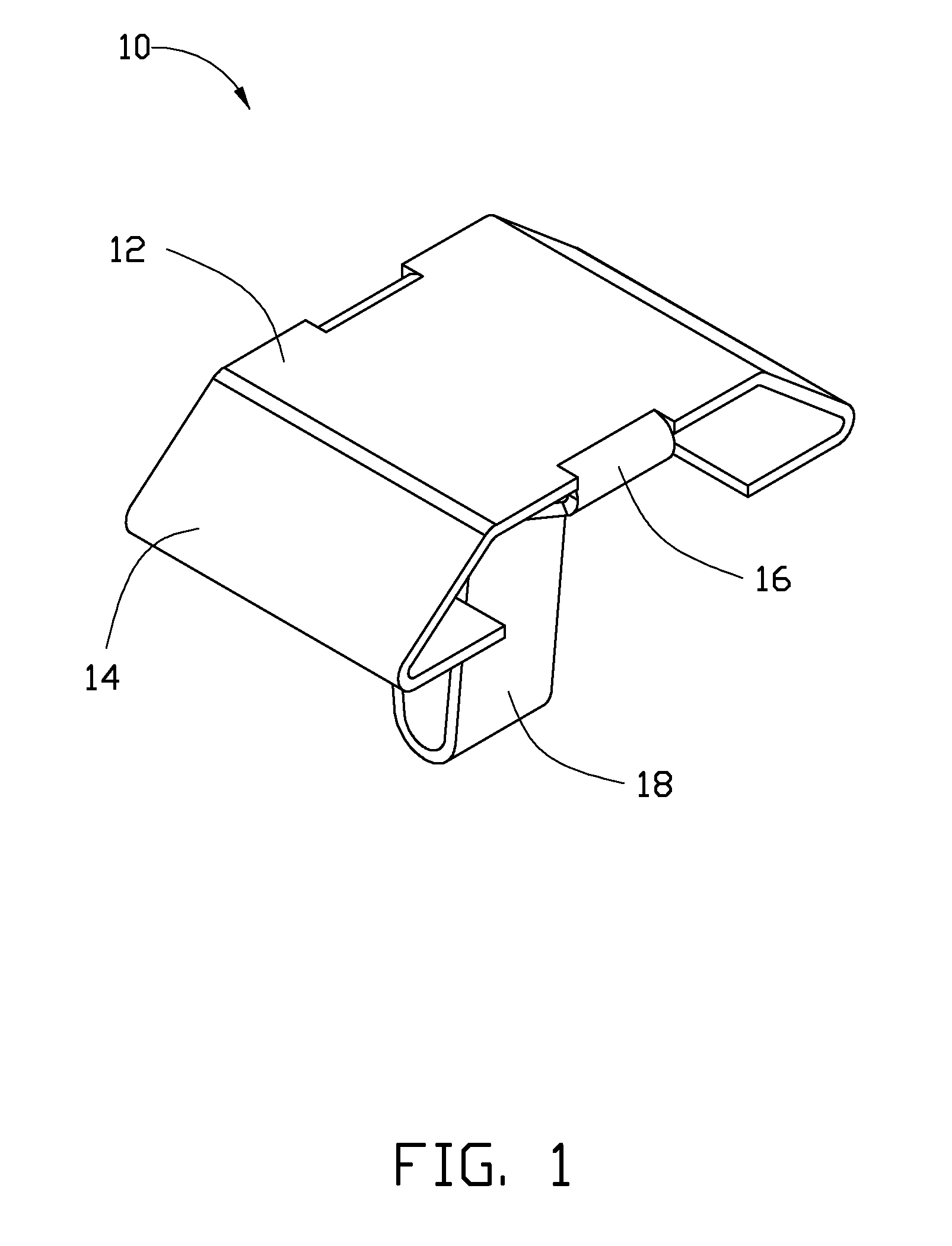
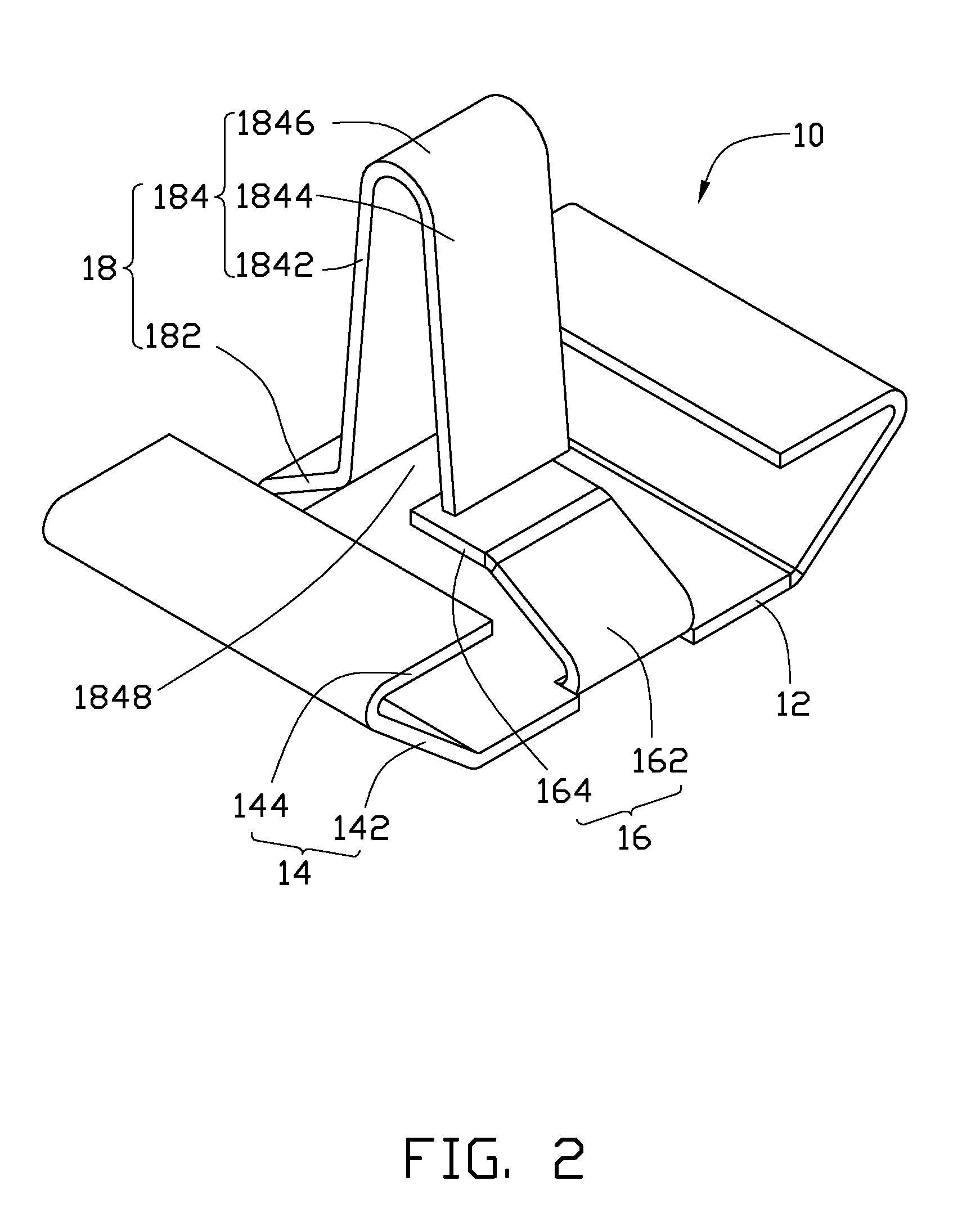
[0013]FIG. 1 and FIG. 2 show a first exemplary elastic sheet structure 10. The elastic sheet structure 10 provides electrical connection between electronic components and a circuit board of an electronic device (not shown). The elastic sheet structure 10 can be formed by punching and bending a metallic sheet.

[0014]The elastic sheet structure 10 includes a plate portion 12, two first wedged portions 14, a second wedged portion 16 and a latching portion 18. The plate portion 12 is a substantially rectangular plate and can be electronically connected to electronic components or a circuit board. The two first wedged portions 14 are formed at opposite sides of the plate portion 12 respectively. The first wedged portions 14 can be formed by bending an extending portion of the periphery of the plate portion 12. The wedged portion 14 includes a first wedged section 142 and a second wedged section 144. The first wedged section 142 extends laterally and downwardly relative to the plate portio...


PUM


Abstract

An elastic sheet structure includes a plate portion, two wedged portion formed at opposite sides of the plate portion, and a latching portion formed another side of the plate portion. The wedged portion and the latching portion can be formed by bending two extending portions of the plate portion downwardly, the wedged portion is used to resist with a circuit board, the latching portion is for insertion into a hole of the circuit board to latch with the circuit board.

Description

BACKGROUND[0001]1. Technical Field[0002]The disclosure relates to conductive contacts, particularly to an elastic sheet structure used in a portable electronic device to electrically connect the electrical components therebetween.[0003]2. Description of Related Art[0004]Electronic products are often equipped with elastic sheet structures between electronic components and a circuit board to electrically connect the electrical components to the circuit board. However, the elastic sheet structures are welded to the electronic components or circuit boards, and accordingly are difficult to replace if needed.[0005]Therefore, there is room for improvement within the art.BRIEF DESCRIPTION OF THE DRAWINGS[0006]Many aspects of the present elastic sheet structure can be better understood with reference to the following drawings. The components in the various drawings are not necessarily drawn to scale, the emphasis instead being placed upon clearly illustrating the principles of the present di...

Claims


Application Information

Patent Timeline
Patent Type & Authority Applications(United States)
IPC IPC(8): H01R4/02
CPCH01R12/585H05K3/308H01R12/718
Inventor TSAO, MEI-TSU
Owner CHI MEI COMM SYST INC
Why Eureka
Try Eureka