Cylindrical lever lock

a technology of lever lock and cylindrical body, which is applied in the direction of mechanical control devices, wing knobs, keyhole guards, etc., can solve the problems of affecting the operation affecting the appearance and function of the locking device, and the inner and outer attachment plates of the conventional art are almost impossible to manufacture using general metal plates. , to prevent the lever from drooping, reduce the number of parts, and facilitate the assembling and installation. the effect of speeding up the a cylindrical lever lock and lever cylindrical and cylindrical lever lock and lever cylindrical and cylindrical technology of cylindrical lever lock and lever lock and cylindrical and cylindrical technology, applied in the field of cylindrical lever lock and which is applied in the field of cylindrical technology, can solve the problem of the lever lock, the appearance and function of the lever lock and the conventional ar

Active Publication Date: 2011-01-13
JUNGHWA TECH
View PDF20 Cites 13 Cited by
  • Summary
  • Abstract
  • Description
  • Claims
  • Application Information

AI Technical Summary

Benefits of technology

[0012]Therefore, the present invention has been made in view of the above problems, and it is an object of the present invention to provide a cylindrical lever lock capable of enduring a strong wrenching force during use, maintaining horizontal position of a lever as well as preventing drooping of the lever even after a longtime use, achieving quicker and easier assembling and installation by reducing the number of parts required for adjustment of part intervals according to thickness of a door, and reducing the manufacturing cost by manufacturing main parts for prevention of the lever drooping using general metal plates.
[0013]In accordance with the present invention, the above and other objects can be accomplished by the provision of a cylindrical lever lock structured in a manner that a rotation spring is elastically connected to a plate shaft through a spring cage and a spring holder, wherein the plate shaft is fixedly inserted in a plate as being fixedly connected with a spring cage cover to prevent separation of the rotation spring, thereby maintaining horizontality of the lever, and the spring holder is engaged doubly with the spring cage and with a stopper protrusion of the spring cage cover through fixing pieces formed on the inside and the outside such that a rotation angle of the lever is restricted and the lever is able to endure even a strong wrenching force. Also, the interval adjustment of the parts according to thickness of the door may be achieved using inner and outer attachment plates, a female screw provided to the outer plate and a male screw provided to a body assembly.

Problems solved by technology

Here, the strong wrenching force is totally transmitted to component parts of the lever lock, thereby damaging or deforming related parts.
As a result, not only the appearance but also the function as a locking device may be deteriorated.
However, the inner and outer attachment plates of the conventional art are almost impossible to manufacture using general metal plates because those are thick and structurally complicated since having the mounting recess, the fixing protrusion and the fixing hole.
Therefore, casting of Zn or Al is required, which will increase the material cost and the process cost, consequently increasing the manufacturing cost.
Also, the inner and outer attachment plates and the movable plate which are essential parts requiring great strength are not sufficiently durable against the wrenching force since being made of non-ferrous metal having low strength.
As a result, the lever lock cannot normally operate, thus finishing the lifespan.
Also, since the movable plate is in the form of a flat panel very susceptible to wrench, a rim of the movable plate may be deformed and spaced, accordingly causing drooping of the lever.
Moreover, friction around the deformed part will hinder a favorable operation of the lever.
Furthermore, since the locking nut is prepared in addition to the interval maintaining plates in order to adjust interval among the component parts according to thickness of the door, the processes will take much time and become complicated during pre-assembling for shipment of the product or during disassembling and installation in the field.

Method used


Image

  • Cylindrical lever lock
  • Cylindrical lever lock
  • Cylindrical lever lock

Examples


Embodiment Construction

[0021]Hereinafter, an exemplary embodiment of the present invention will be described in detail with reference to the accompanying drawings. In the following description, like elements are cited by like reference numerals while generally-known structures and functions will not be explained in detail so as not to obscure the present invention.

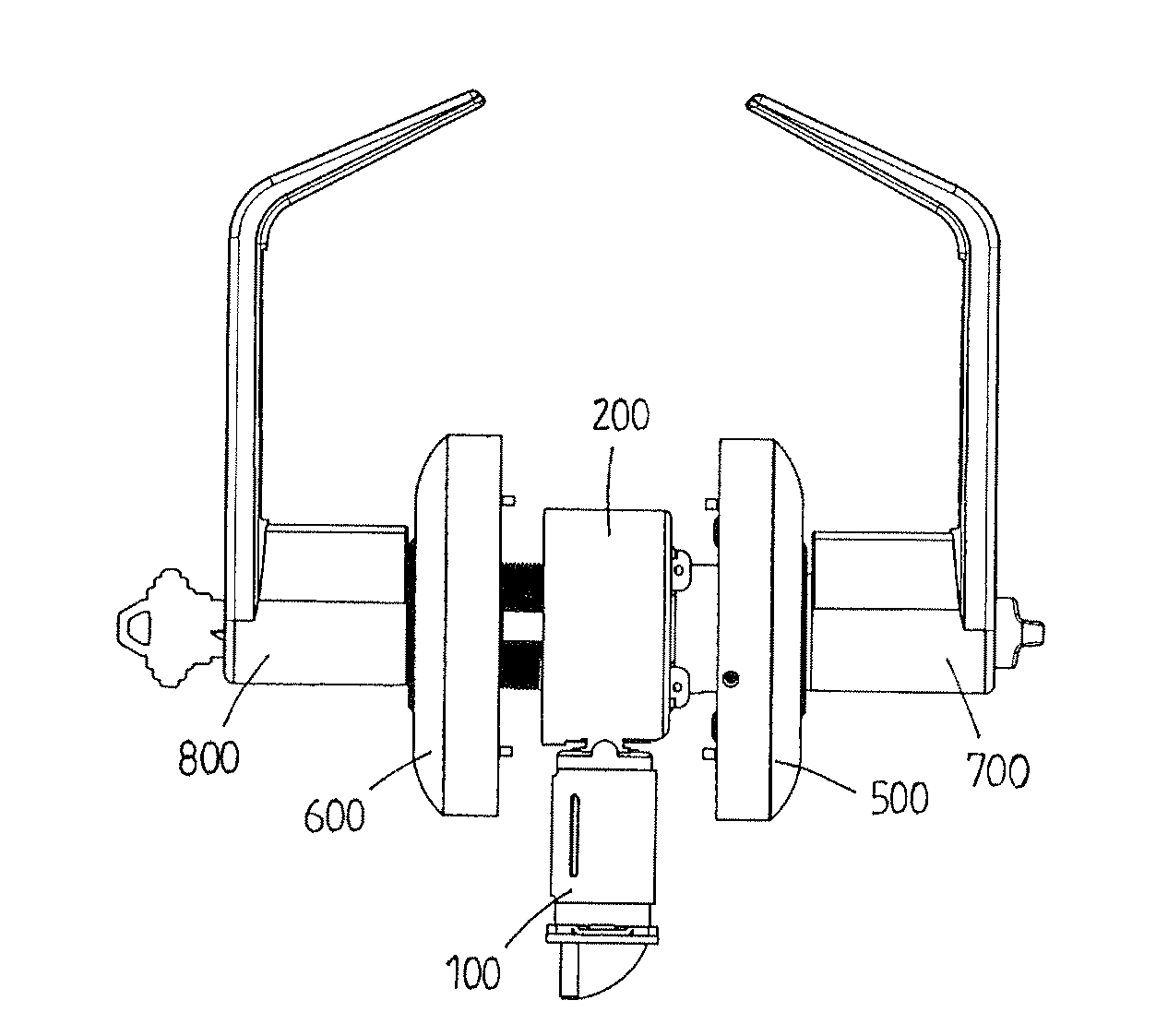
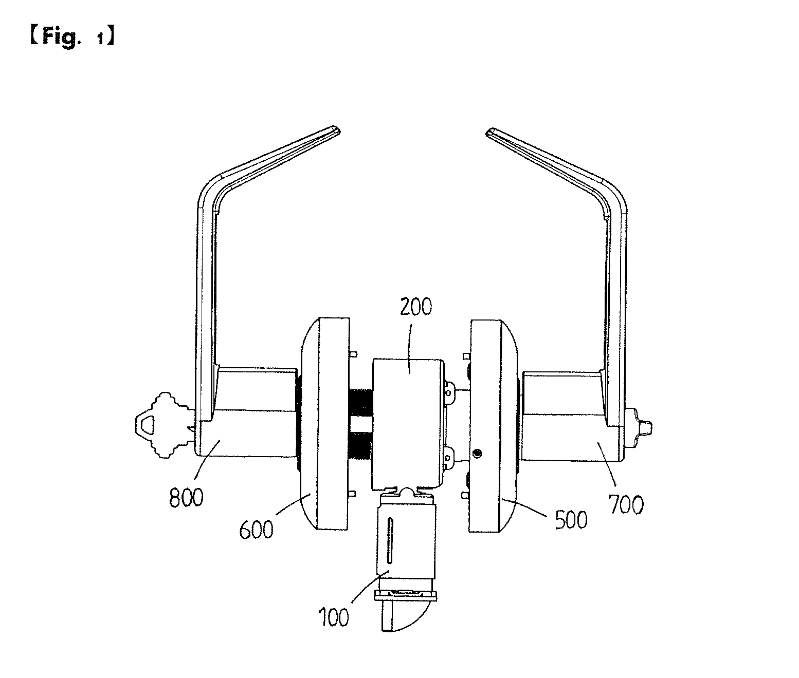
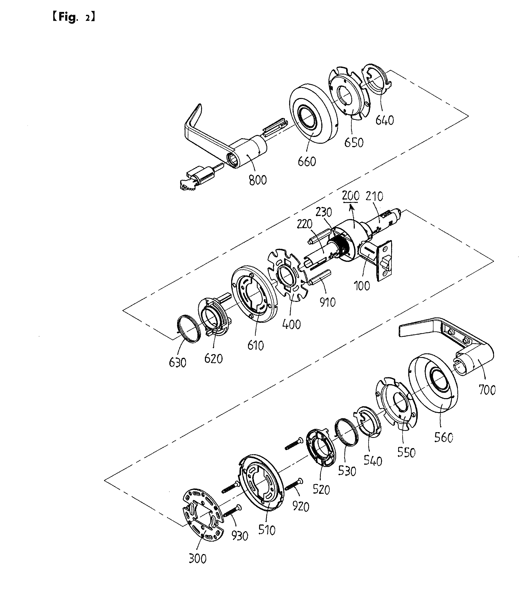
[0022]FIG. 1 is a plan view showing the structure of a cylindrical lever lock according to an embodiment of the present invention, and FIG. 2 is an exploded perspective view of the cylindrical lever lock. The cylindrical lever lock includes a latch assembly 100 connected to a front of a body assembly 200. Inner and outer attachment plates 300 and 400, inner and outer plate assemblies 500 and 600, and inner and outer levers 700 and 800 are sequentially connected to both sides of the body assembly 200 disposed between each pair of the above parts.

[0023]The latch assembly 100, the body assembly 200 and the inner and outer levers 700 and 800 of this...


PUM


Abstract

A cylindrical lever lock using a lever as a handle for convenient use by even the disabled and the old is disclosed. Since plate shafts, spring holders and spring cage covers constituting the cylindrical lever lock are made of general metal plates, the material cost and the prime cost may be reduced. In addition, the spring holders are connected through double engagements with spring cages and the spring cage covers. Therefore, deformation of parts or drooping of levers may be prevented in spite of an excessive force applied. Furthermore, assembling and disassembling of the parts can be quickly and easily performed by achieving adjustment of intervals of the parts according to thickness of a door using a female screw of an outer attachment plate and a male screw of a boy assembly.

Description

BACKGROUND OF THE INVENTION[0001]1. Field of the Invention[0002]The present invention relates to a cylindrical lever lock capable of preventing a lever from drooping or malfunctioning due to deformation of related parts although being repetitively used or applied with a strong wrenching force during opening and closing of a door, and also capable of reducing the manufacturing cost.[0003]2. Description of the Related Art[0004]A door lock is generally used in various public facilities including public or commercial buildings such as schools, government and public offices, hospitals, and hotels, and such a door lock mostly employs a cylindrical lever lock using a thin and long lever as a handle so that even the disabled and the old are able to conveniently use the lever lock. The lever additionally employs a spring to return the lever rotated to open or close the door to its initial position.[0005]Generally, the lever of the cylindrical lever lock is mounted in a horizontal position fo...

Claims


Application Information

Patent Timeline
Patent Type & Authority Applications(United States)
IPC IPC(8): E05C1/12
CPCE05B3/065Y10T70/5832Y10T70/8541Y10T292/0974Y10T292/57Y10T292/82Y10T292/85Y10T292/91
Inventor CHO, CHANG SOO
Owner JUNGHWA TECH
Why Eureka
Try Eureka