
Low-energy building, particularly greenhouse or stabling

a low-energy building and greenhouse technology, applied in solar heating energy, space heating and ventilation, agricultural machinery and equipment, etc., can solve the problems of high energy requirements, insufficient transfer of energy to commercial buildings with large glass surfaces, greenhouses, etc., and achieve the effect of reducing the temperature, avoiding overheating the whole building, and increasing the temperature in the interspa

Inactive Publication Date: 2011-01-13
KRECKE EDMOND D
View PDF4 Cites 9 Cited by
  • Summary
  • Abstract
  • Description
  • Claims
  • Application Information

AI Technical Summary

Benefits of technology

[0011]If necessary, fresh air from the outside may alternatively be fed in for tempering. Basically, however, a temperature stabilization is already achieved by a cycle, because the air between the windows heats strongly up in case of incident solar radiation so that it is essentially warmer than the temperature in the heat reservoir. The warm air is guided through the heat reservoir, wherein a heat exchange extracting heat from the air is caused. The so cooled air again flows back into the interspaces, and lowers the temperature between the windows, by what an overheating of the whole building is avoided, particularly during summer.
[0024]In this manner, a considerable saving of heat may be achieved, even in case of badly insulated buildings like greenhouses, and stablings. Depending on the climate zone, even zero-energy greenhouses may be provided.
[0029]The pipe-in-pipe heat exchangers installed in the terrestrial heat reservoir preferably consist of flexible. Metallic pipes, which can easily be installed, and ensure a good heat exchange.

Problems solved by technology

It is a disadvantage of this known technology that it cannot or only unsufficiently be transferred to commercial buildings with large glass surfaces, like stablings, and greenhouses.
Despite the low temperatures often prevailing in those buildings, high amounts of energy are necessary to keep the inner space of the building on the wanted temperature level, due to the thermal insulation often being poor just in the case of large buildings.

Method used


Image

  • Low-energy building, particularly greenhouse or stabling
  • Low-energy building, particularly greenhouse or stabling
  • Low-energy building, particularly greenhouse or stabling

Examples


Embodiment Construction

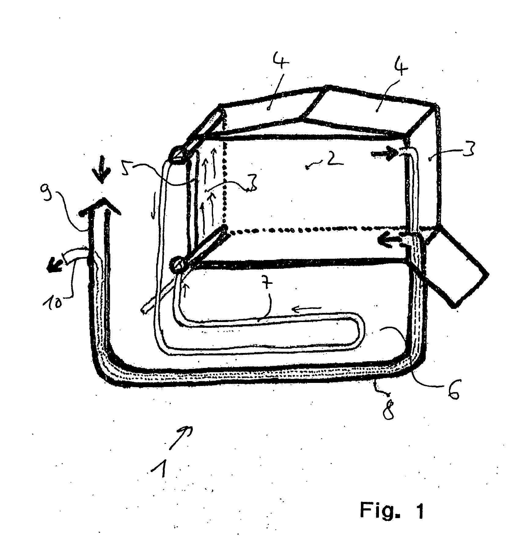
[0041]FIG. 1 schematically shows a building 1, which particularly is formed as greenhouse.

[0042]The building 1 comprises an inner space 2 which is surrounded by walls 3, and roof areas 4 particularly consisting of windows. Thereby, the walls 3, and the roof areas 4 are formed as double windows made of plastics, plastics foil, or glass. Interspaces 5 are defined by the double windows. Under the building, there is a terrestrial heat reservoir 6 which is connected with the interspace 5 via a conduit 7. Air is pumped out of the terrestrial heat reservoir 6 into the interspaces 5 via the conduit 7. In times of low temperature, the air in the terrestrial heat reservoir 6 is heated, and forms a temperature barrier in the interspaces 5. If, for example, air of 15° C. pumped through the interspaces, this has the effect of the ambient temperature of the building 1, having 15° C., only.

[0043]In times of high temperature, the heat may in contrast be led away out of the interspaces 5, whereby th...


PUM


Abstract

A building is disclosed, with which the air may be guided from a heat reservoir into an interspace, and / or from the interspace into the heat reservoir through conduits.

Description

FIELD OF THE INVENTION[0001]The invention relates to a low-energy building, preferably formed as greenhouse, or stabling. In particular, the invention relates to a greenhouse, a stabling, or a fish farm formed as zero-energy building.BACKGROUND OF THE INVENTION[0002]Low-energy houses, and zero-energy houses are known. Particularly, buildings are known, which have building wall with fluid lead-throughs, by means of which a temperature barrier may be formed. The German patent application publication DE 298 04 095 A1 (inventor: Edmond D. Krecke) for example shows such a low-energy house. Zero-energy houses may even be provided in northern degrees of latitude by means of a geothermal heat reservoir, which is loaded during summer, and unloaded during winter, as well as by means of temperature barriers consisting of fluid conduits arranged in the walls.[0003]It is a disadvantage of this known technology that it cannot or only unsufficiently be transferred to commercial buildings with larg...

Claims


Application Information

Patent Timeline
Patent Type & Authority Applications(United States)
IPC IPC(8): E04H14/00F28D7/10F24F11/00F24J3/08F25B29/00A01G9/14
CPCF24F5/0017A01K1/0076F24F5/005F24F5/0075F24F12/006F24F2005/0057Y02B10/20Y02B10/24Y02B30/547Y02B30/92Y02E60/147Y02B10/40Y02B30/563F24J2/0433F28D7/10F28D20/0052A01G9/1469A01G9/245F24F5/0046Y02A30/272Y02A40/76F24S20/63Y02A30/00Y02A40/70Y02A40/25Y02B30/54Y02B30/56Y02B30/90Y02E60/14Y02P60/14Y02P60/50Y02E10/40Y02P60/12Y02E10/44
Inventor KRECKE, EDMOND D.
Owner KRECKE EDMOND D
Learn More