Method and device for machining a part by abrasion

Inactive Publication Date: 2011-01-06
SN DETUDE & DE CONSTR DE MOTEURS DAVIATION S N E C M A
View PDF16 Cites 7 Cited by
  • Summary
  • Abstract
  • Description
  • Claims
  • Application Information

AI Technical Summary

Benefits of technology

[0010]Thanks to the invention, the pin serves as support and as driving means for the abrasive liquid that exerts the abrasion function. The pin therefore participates indirectly in the machining of the part via the abrasive liquid. The method thus has all the advantages of abrasion machining, without having the drawbacks thereof In particular, since the pin is not used directly for abrading the part, it is less consumed or fouled by it and its shape remains more stable. This enables the method to be repeated with constant good quality, only the liquid being consumed. Moreover, it is easy to adapt the method to the part to be machined, by adapting the nature of the abrasive liquid and the various parameters that may be involved in the method, including the distance between the part and the pin, and therefore the pressure exerted by the pin on the liquid and the part, the rotation speed of the pin, the possible speed of displacement of the pin relative to the part, the amount of liquid injected between the part and the pin, etc.
[0011]Finally, the method of the invention includes characteristics both of a milling method and a grinding wheel method: of a milling method since it employs a rotated pin and of a grinding wheel method since the material is removed from the part by abrasion. Thus, the use of a rotating pin gives the method of the invention great precision and controllability in its implementation, whereas the abrasion of the part may take place very progressively, since the action of the abrasive liquid, driven by the pin, is exerted tangentially to the abraded surface of the part.
[0015]Preferably, since the pin is formed from a material having a certain hardness and the part is formed from a material having a certain hardness, the abrasive material of the abrasive liquid has a hardness between the hardness of the pin and the hardness of the part. Thus, it is guaranteed that the liquid has an abrasive effect on the part but not on the pin, and that the pin is not consumed, thereby improving the stable reproducibility of the method over time.
[0016]According to one embodiment, the pin is also driven so as to move translationally along the part, for example in a manner similar to that of a conventional lateral milling operation. This makes it possible to machine a larger area of the part with the pin, in a controllable and precise manner.

Problems solved by technology

Problems arise when machining parts formed from a CMC material, irrespective of the method chosen.
The methods most often used, which are grinding and water jet cutting, are either expensive or do not provide high-precision machining.
This is particularly problematic when the parts are of complex shape, especially in the aeronautical field that imposes standards with low tolerances.
Moreover, the use of a tool such as a grinding wheel or a milling cutter for machining a CMC part causes fouling of this tool, since particles of the CMC part become lodged between the grains of the material forming the tool.
Furthermore, electron beam cutting and ultrasonic cutting are complex operations that are onerous to implement.

Method used


Image

  • Method and device for machining a part by abrasion
  • Method and device for machining a part by abrasion

Examples


Embodiment Construction

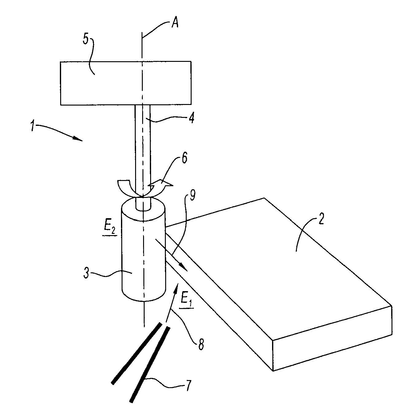
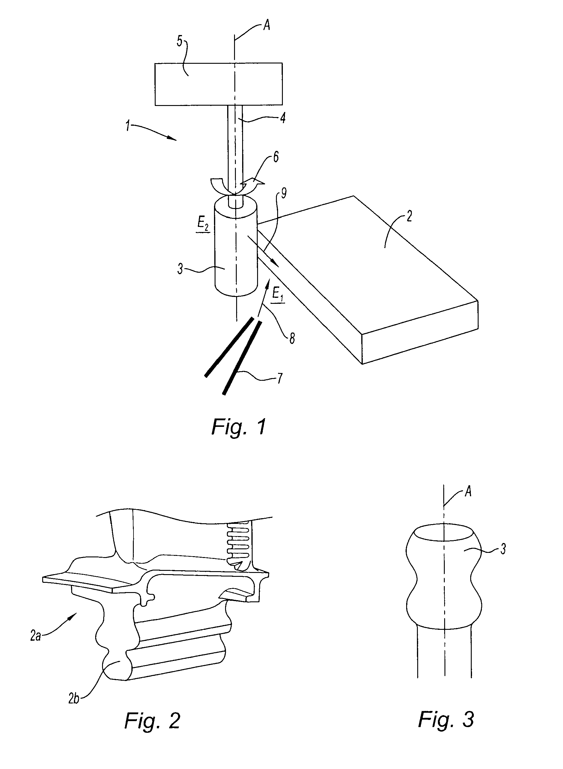
[0023]Referring to FIG. 1, a device 1 for the abrasion machining of a part 2 comprises a pin 3, of axis A, mounted on a shaft 4 that also extends along the axis A and is itself supported by a frame 5. The pin 3 may also be denoted by the expression “rotary head”3. The shaft 4 can be rotated (as represented schematically by the arrow 6 in FIG. 1) by rotary drive means, not shown, comprising here an electric motor, said means being mounted on the frame 5. The shaft 4 then rotates the pin 3 which is integral therewith. The device 1 also includes means (not shown) for positioning and fixing the part 2 relative to the frame 5, in a manner known to those skilled in the art.

[0024]The device also includes all the elements of a center (or device) for conventional machining (motors, position sensors, processing unit, etc.). It is not necessary to describe them in detail because their structure and their function are well known to a person skilled in the art who, to implement the device and th...


PUM

PropertyMeasurementUnit
Pressureaaaaaaaaaa
Distanceaaaaaaaaaa
Hardnessaaaaaaaaaa

Abstract

The abrasion machining method according to the invention, for abrading a part that cannot be machined by conventional means, comprises the following steps:a pin is placed at a certain distance from the part to be machined, so that there is no contact between the part and the pin;the pin is driven so as to rotate;an abrasive liquid is injected between the rotating pin and the part in order to abrade the latter; andthe pin is moved translationally along the part.Thanks to the method, the part may be machined precisely and reproducibly.

Description

BACKGROUND OF THE INVENTION[0001]The present invention relates to the machining of parts and more particularly to the machining of parts made of ceramic matrix composites.[0002]Ceramic matrix composites are generally denoted by the acronym CMC. These composites are formed from a ceramic matrix, for example based on carbon (C) or silicon carbide (SiC) within which fibers of a material having good tensile strength properties extend so as to take up the forces to which the composite is subjected. The ceramic matrix provides the bonding between the fibers, ensures that they are spaced apart and transfers the forces to which the CMC part is subjected to said fibers.DESCRIPTION OF THE PRIOR ART[0003]CMC materials are used especially for the manufacture of parts for applications in the aeronautical field, in particular for the manufacture of turbine blades, turbine seals, combustion chambers, nozzles, guide vanes, etc. CMC parts are abradable (i.e. they can be abraded). The known methods f...

Claims


Application Information

Patent Timeline
IPC IPC(8): B24B1/00
CPCB24B1/00B24B37/00B24B19/14B24B19/009
Inventor PEREZ-DUARTE, ALEXIS
Owner SN DETUDE & DE CONSTR DE MOTEURS DAVIATION S N E C M A
Why Eureka
Try Eureka