
Method for warning the driver of a motor vehicle of increased risk of an accident

a technology for motor vehicles and drivers, applied in the direction of brake systems, brake components, transportation and packaging, etc., can solve the problem of weaker warning signals, and achieve the effect of reducing the severity of the accident and increasing the risk of an acciden

Inactive Publication Date: 2011-01-06
ROBERT BOSCH GMBH
View PDF8 Cites 9 Cited by
  • Summary
  • Abstract
  • Description
  • Claims
  • Application Information

AI Technical Summary

Benefits of technology

[0005]An object of the present invention is to prompt the driver of a motor vehicle, whenever there is an increased risk of an accident, to take measures to prevent the accident or to reduce the severity of the accident.
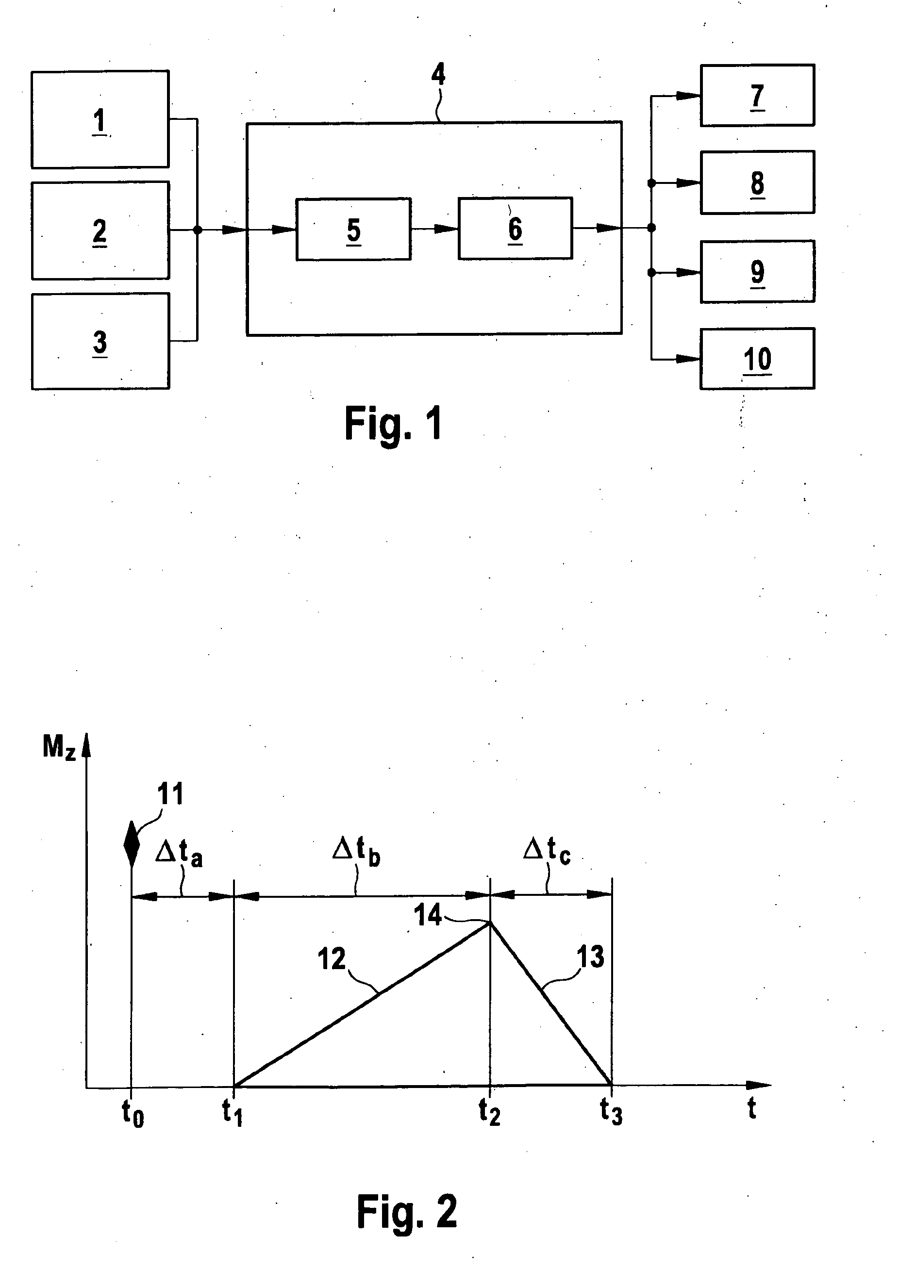
[0010]The change in the yaw rate may also be subjected to additional conditions. It may be advantageous for the rising gradient by which the yaw rate is increased to be maximized so that, when seen over time, a pulse-like change in the yaw rate is implemented. It may likewise be advantageous to also maximize the time-dependent falling gradient by which the yaw rate is reduced again. On the whole, this results in a yaw rate pulse with a sudden increase or decrease in the yaw rate change.
[0011]For safety reasons, the yaw rate is altered only in stable driving states to prevent further destabilization from occurring in an unstable driving state. For example, the sideslip angle of the motor vehicle is considered to be a measure of the stability of the driving state, a change in the yaw rate being implemented only when the sideslip angle is below an acceptable limiting value.
[0014]If there are multiple active control systems in the vehicle by which a change in the yaw rate is achievable, then a plurality of control systems may also be used at the same time for implementation of the yaw pulse. The dead time between the point in time of accident detection and triggering of the yaw pulse may thus be minimized, and a high rising gradient of the yaw pulse may be achieved. Furthermore, feedback effects on the steering wheel, which could otherwise irritate the driver, may be avoided.

Problems solved by technology

For example, the change in the yaw rate may correlate with the anticipated severity of the accident, so that the greater the anticipated damage, the stronger the warning signal turns out to be.

Method used


Image

  • Method for warning the driver of a motor vehicle of increased risk of an accident
  • Method for warning the driver of a motor vehicle of increased risk of an accident
  • Method for warning the driver of a motor vehicle of increased risk of an accident

Examples


Embodiment Construction

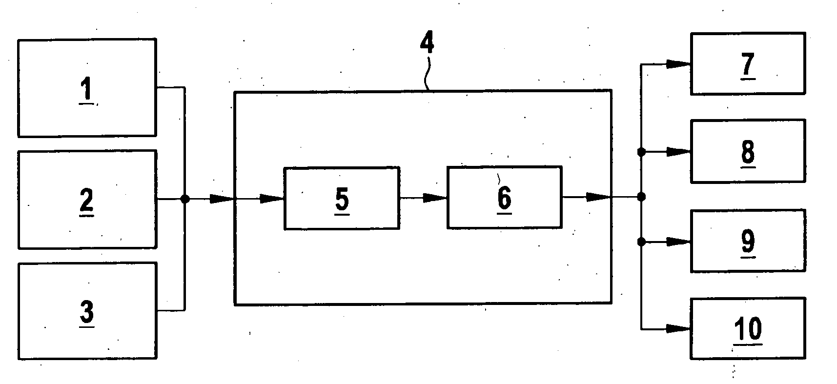
[0017]The flow chart according to FIG. 1 shows that in a first method step 1, the risk of an imminent collision or another accident is detected with the help of a vehicle accident detection unit. Accident detection units, e.g., radar, ultrasound or infrared sensors and video-based systems, are used for this purpose. These systems may also be used according to method step 2 to detect whether the vehicle is leaving the predefined roadway or lane. In addition or as an alternative to the aforementioned noncontact detection units, GPS (Global Positioning Systems) may also be used for determining the position of a vehicle in conjunction with an electronically stored road map.

[0018]In another method step 3, the driving state of the motor vehicle is determined using extra sensors provided in the sensor system, e.g., acceleration sensors and yaw rate sensors, the driving state possibly also being ascertained by calculation, if necessary, e.g., by so-called observer models.

[0019]The data coll...


PUM


Abstract

In a method for warning the driver of a motor vehicle, the yaw rate is altered in the event of an increased risk of an accident, and the change in the yaw rate serves to warn the driver of the increased risk state.

Description

BACKGROUND OF THE INVENTION[0001]1. Field of the Invention[0002]The present invention relates to a method for warning the driver of a motor vehicle of an increased risk of an accident.[0003]2. Description of Related Art[0004]Published German patent document DE 10 2004 030 756 A1 describes a method for kinesthetic warning of the driver of a motor vehicle in situations where there is an increased risk of a collision. The motor vehicle is equipped with an object detection sensor, which is designed as a radar sensor, an ultrasonic sensor or a video sensor, for example, and this makes it possible to ascertain the distance and relative speed of an object with respect to one's own vehicle. In conjunction with additional input data, e.g., one's own vehicle speed, a hazard value for a collision with a corresponding object may be ascertained therefrom. When there is an increased risk of a collision, the brake mechanism is automatically triggered in the vehicle to warn the driver, and a brakin...

Claims


Application Information

Patent Timeline
IPC IPC(8): B60Q1/00B60W30/08B60W30/18B60W50/08
CPCB60T8/17558B60T2201/024B60T2260/02B60W30/08B60W30/09B60W30/095B62D15/029B60W50/14B60W2420/52B60W2520/14B62D6/003B62D15/0265B60W30/18172B60W50/16B60W2720/14B60W2420/408
Inventor ROELKE, VOLKERFREESS, JASCHAKNOOP, MICHAELRENTSCHLER, TOBIAS
Owner ROBERT BOSCH GMBH
Learn More