
Driver arrangement for light emitting diodes

a technology of light-emitting diodes and driver arrangements, which is applied in the direction of electric variable regulation, process and machine control, instruments, etc., can solve the problems of evident drawbacks in the control arrangemen

Inactive Publication Date: 2011-01-06
OSRAM GMBH
View PDF3 Cites 8 Cited by
  • Summary
  • Abstract
  • Description
  • Claims
  • Application Information

AI Technical Summary

Benefits of technology

[0013]minimizing high frequency ripple on the LED current while optimizing LED current rise and fall times (this is a typical requirement for a high performance colour management system),
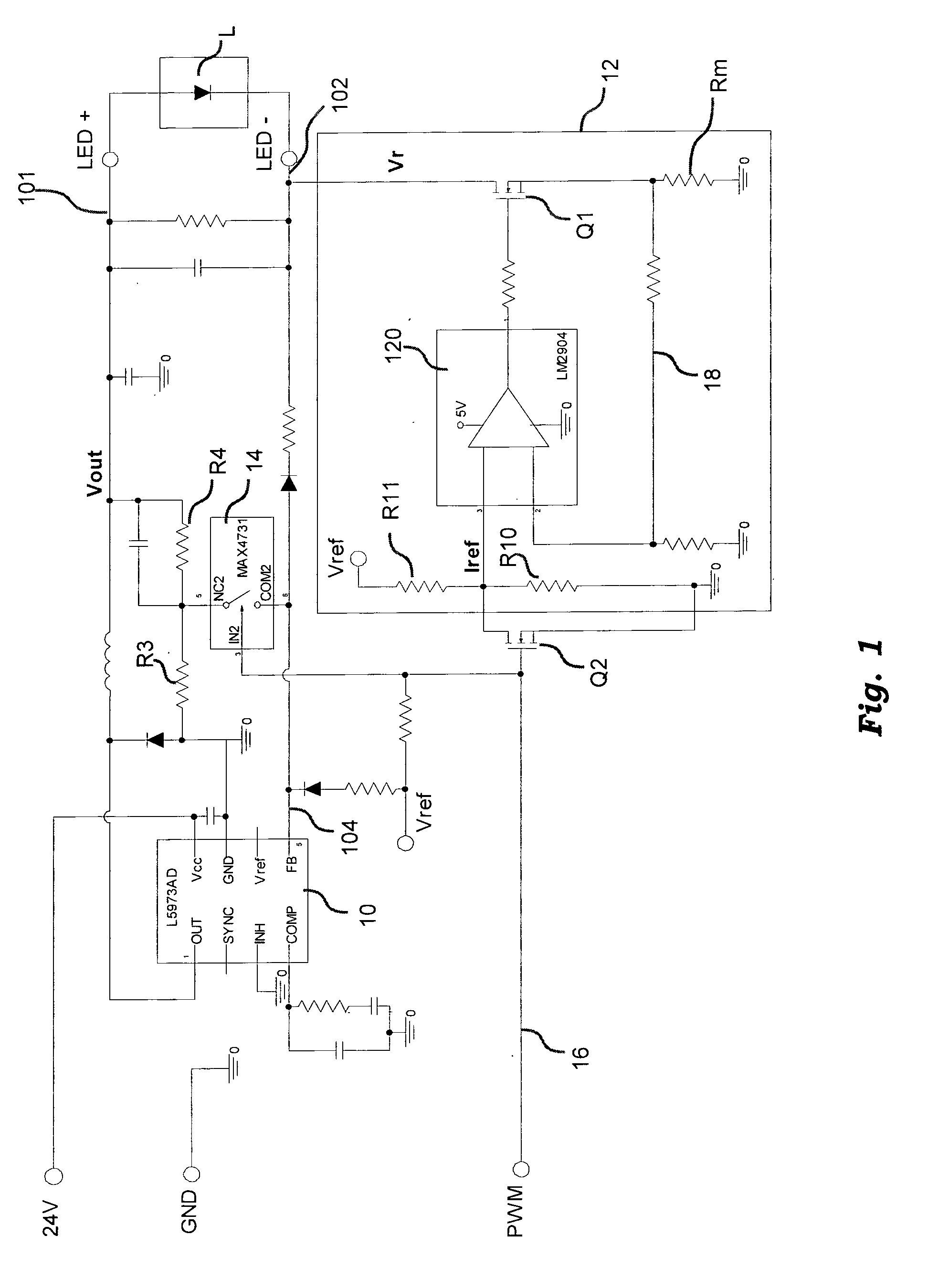
[0019]In an embodiment, a double stage (cascade) LED driver arrangement is provided with a simple, very effective control strategy involving:
[0022]In an embodiment, the arrangement described herein may be controlled based on a smart procedure in order to minimize losses without losing a fast dynamic performance.

Problems solved by technology

Despite its effectives, such a control arrangement exhibits evident drawbacks, especially in the case of the PWM dimmed applications.

Method used


Image

  • Driver arrangement for light emitting diodes
  • Driver arrangement for light emitting diodes

Examples


Embodiment Construction

[0024]In the following description, numerous specific details are given to provide a thorough understanding of embodiments. The embodiments can be practiced without one or more of the specific details, or with other methods, components, materials, etc. In other instances, well-known structures, materials, or operations are not shown or described in detail to avoid obscuring aspects of the embodiments.

[0025]Reference throughout this specification to “one embodiment” or “an embodiment” means that a particular feature, structure, or characteristic described in connection with the embodiment is included in at least one embodiment. Thus, the appearances of the phrases “in one embodiment” or “in an embodiment” in various places throughout this specification are not necessarily all referring to the same embodiment. Furthermore, the particular features, structures, or characteristics may be combined in any suitable manner in one or more embodiments.

[0026]The headings provided herein are for...


PUM


Abstract

A driver arrangement for LEDs may include a PWM controller to deliver a feed voltage between an output line and a ground output line, said controller having a pin, a current regulator to regulate the feed current, a switch to connect said pin to a scaled-down version of the voltage on the first output line, and a control line to receive a signal to produce dimming, said control line coupled to said regulator and said switch to couple said regulator to a reference voltage and control switching, whereby: in one of the levels of a PWM control signal, said regulator interrupts said feed current, the voltage on said ground output line is floating, and in the other levels, said regulator is coupled to said reference voltage, said switch disconnects said pin from said voltage on the output line and the voltage on said ground output line is regulated.

Description

FIELD OF THE INVENTION[0001]The disclosure relates to techniques for driving Light Emitting Diodes or LEDs.[0002]The disclosure was devised by paying specific attention to its possible use in driving LEDs used as lighting sources. However, reference to this possible application is not to be construed in a limiting sense of the scope of the disclosure.DESCRIPTION OF THE RELATED ART[0003]Driving LEDs, especially LEDs used for lighting purposes, poses a number of basic requirements to be met.[0004]Compactness and high electrically efficiency of the driver may represent a first requirement, in view of the expected large lots of production. High performance PWM (Pulse Width Modulation) dimming capability (e.g. LED current rise / fall times lower than, say, 5 microseconds) represents an other requirement. Very low LED current ripple (e.g. less than 1%) is another desired feature.[0005]High efficiency and compactness may be achieved with a single-stage switching arrangement at the expense of...

Claims


Application Information

Patent Timeline
Patent Type & Authority Applications(United States)
IPC IPC(8): H05B41/36H05B44/00
CPCH05B33/0815Y02B20/347H05B33/0851H05B45/10H05B45/00Y02B20/30H05B45/37
Inventor CECCONELLO, NICODE ANNA, PAOLOZANFORLIN, NICOLA
Owner OSRAM GMBH
Learn More