
Linearity of an RF receive path by spurious tone suppression

a spurious tone suppression and linearity technology, applied in the field of rf signal processing, can solve the problems of reducing signal fidelity, reducing the linearity of the amplifier used, and increasing the problems of interfering between the various subsystems, so as to increase the linearity of the receive path and increase the linearity of the rf signal receive path

Active Publication Date: 2010-12-30
TEXAS INSTR INC
View PDF3 Cites 3 Cited by
  • Summary
  • Abstract
  • Description
  • Claims
  • Application Information

AI Technical Summary

Benefits of technology

The patent describes a method, system, and mobile device for improving the linearity of an RF signal receive path. This is achieved by measuring the signal and injecting an anti-spur tone into the ground of the path to reduce nonlinearity. The system includes a spurious tone suppressor and a controller to determine the error signal and reconfigure the suppressor to reduce nonlinearity. The technical effect is improved signal quality and reduced distortion in RF signal transmission.

Problems solved by technology

As chip size is scaled downward, interactions between the various subsystems become increasingly problematic due to their closer proximity and reduced geometries.
Some interactions may reduce the linearity of an amplifier used to amplify a received RF signal.
Nonlinearity may reduce signal fidelity and lead to a reduced operating range of the transceiver.

Method used


Image

  • Linearity of an RF receive path by spurious tone suppression
  • Linearity of an RF receive path by spurious tone suppression
  • Linearity of an RF receive path by spurious tone suppression

Examples


Embodiment Construction

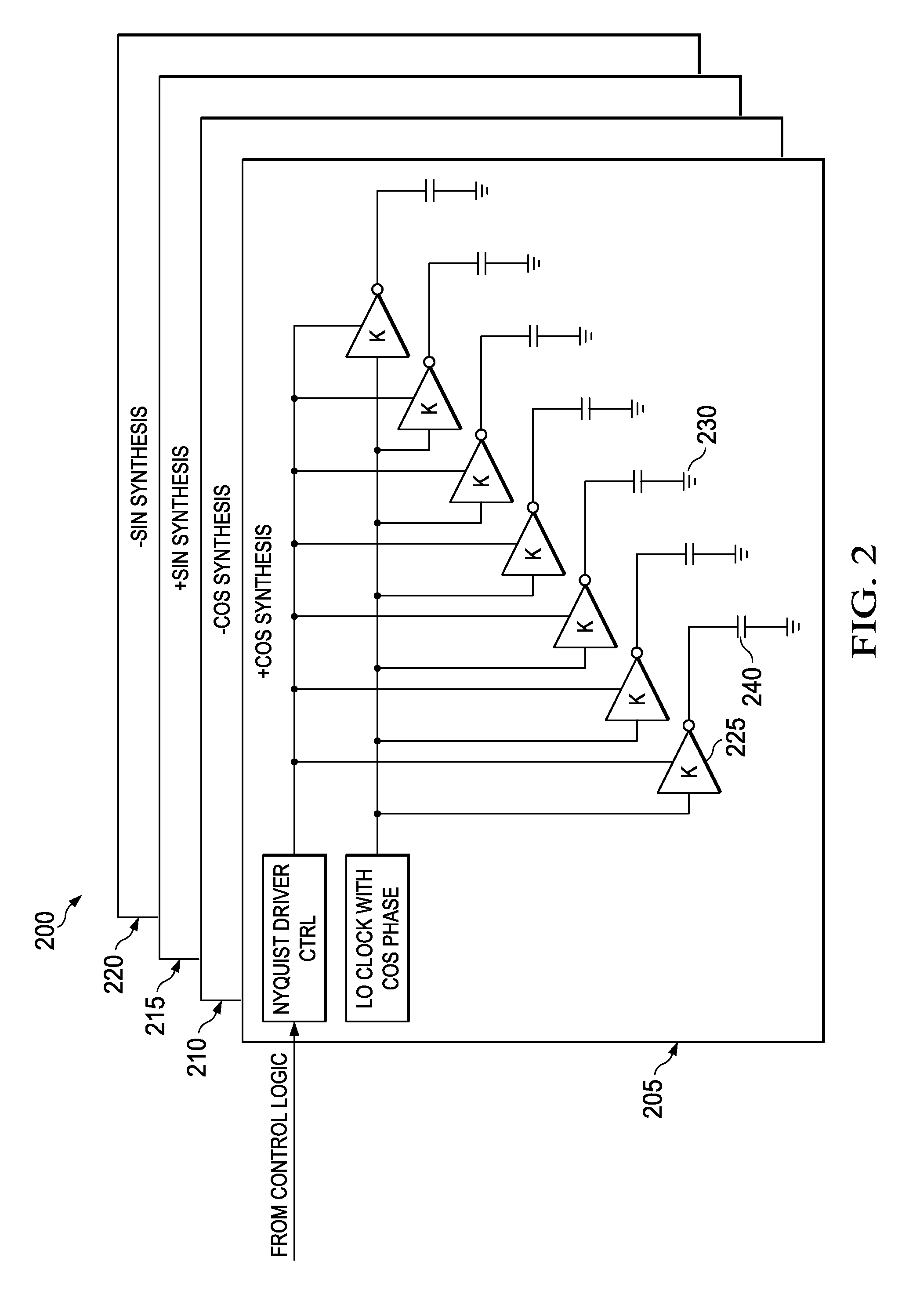
[0014]Embodiments described herein employ a technique of using an adaptive spur suppression system to provide a spur reduction tone to an RF receive path to increase linearity of the path. This technique also provides the ability to efficiently and rapidly determine the phase and amplitude of the spur reduction tone.

[0015]Methods have been developed to reduce the effect of noise spurs caused by switching power supplies on such transceivers. One method involves injecting an anti-spur current into the ground of the transceiver. The anti-spur current is adaptively configured to partially cancel the noise spurs caused by the switching power supply. Such a method is described in U.S. patent application Ser. No. 11 / 679,119 (the '119 application) filed on Feb. 26, 2007, and incorporated by reference herein in its entirety.

[0016]Sources of periodic signals may also result in noise spurs. For example, a local oscillator (LO) may operate with a frequency ωLO in an RF receive path to down conv...


PUM


Abstract

A method of increasing linearity of an RF signal receive path includes measuring a signal amplified by the receive path. The receive path has a local oscillator operating at an LO frequency and a ground. An error signal is determined from the amplified signal, the error signal being representative of the nonlinearity. An anti-spur tone is injected into the ground. The anti-spur tone has a frequency about equal to the LO frequency and an amplitude and phase that are determined to increase the linearity of the receive path.

Description

TECHNICAL FIELD[0001]This application is directed, in general, to RF signal processing and, more specifically, to improving linearity of a received RF signal.BACKGROUND[0002]The demand for wireless products has been growing in recent years, resulting in intensive efforts to develop single chips that have reduced cost, power dissipation and chip size. As chip size is scaled downward, interactions between the various subsystems become increasingly problematic due to their closer proximity and reduced geometries. This is especially true for systems such as wireless transceivers, which require processing of low level and high frequency signals in an environment where digital signals are also employed.[0003]Some interactions may reduce the linearity of an amplifier used to amplify a received RF signal. Nonlinearity may reduce signal fidelity and lead to a reduced operating range of the transceiver. Thus, it is desirable to mitigate interactions that lead to nonlinearity of the amplifier....

Claims


Application Information

Patent Timeline
Patent Type & Authority Applications(United States)
IPC IPC(8): H04B17/00
CPCH04B17/309H04B17/21
Inventor CHOO, HUNSOOELAHI, IMTINANMUHAMMAD, KHURRAM
Owner TEXAS INSTR INC
Learn More