Process and apparatus for producing thick-walled plastic components

a technology of plastic components and processing equipment, applied in auxillary shaping equipment, instruments, applications, etc., can solve problems such as inability to produce large gates, voids or warpages, and sink marks, and achieve the effect of not being able to produce large gates at all

Inactive Publication Date: 2010-12-30
BAYER MATERIALSCIENCE AG
View PDF5 Cites 21 Cited by
  • Summary
  • Abstract
  • Description
  • Claims
  • Application Information

AI Technical Summary

Problems solved by technology

If in the process the sprue or the region on the component close to the sprue is sealed as a result of solidification of the plastic melt (sealing-time) before the volume contraction of the component during the cooling phase has been fully concluded, this can result in sink marks, voids or warpage.
On the other hand, however, in the case of the separation of the sprue from the component relatively large or thick sprue marks are disadvantageous, because quality-reducing eruptions of material or separation marks may arise in this case.
Contaminations by dust, chips or the like may also arise in this case, which is unacceptable, for instance, in the case of clean-room conditions which are frequently demanded.
Often large gates are not possible at all, because the component offers no space for this.
In addition, in the case of optical components many regions that are theoretically usable for the placement of a gate often fall out of consideration for aesthetic reasons, by reason of the transparent material.
Furthermore, thick sprues give rise, as a rule, to additional costs as a result of a reworking of the gate mark (separation mark).
In addition, relatively large or thick sprues give rise to an increased consumption of material.

Method used


Image

  • Process and apparatus for producing thick-walled plastic components
  • Process and apparatus for producing thick-walled plastic components
  • Process and apparatus for producing thick-walled plastic components

Examples


Embodiment Construction

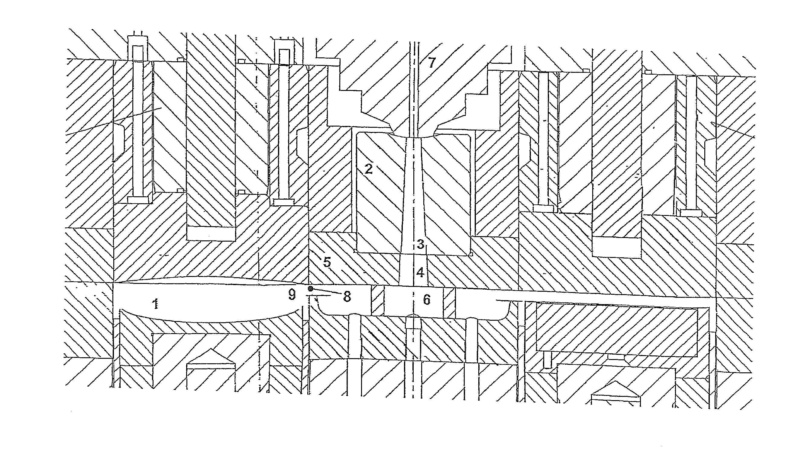
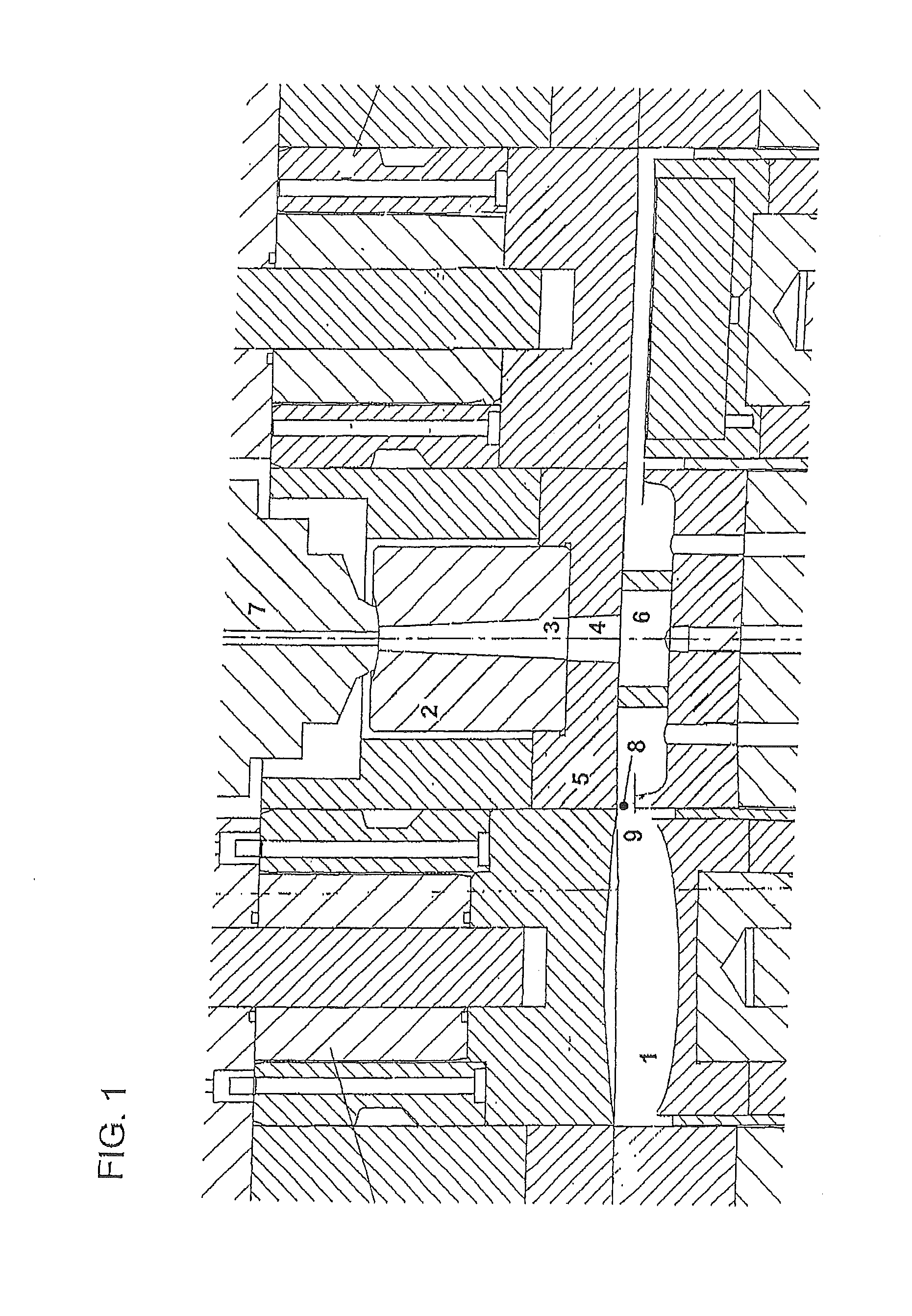
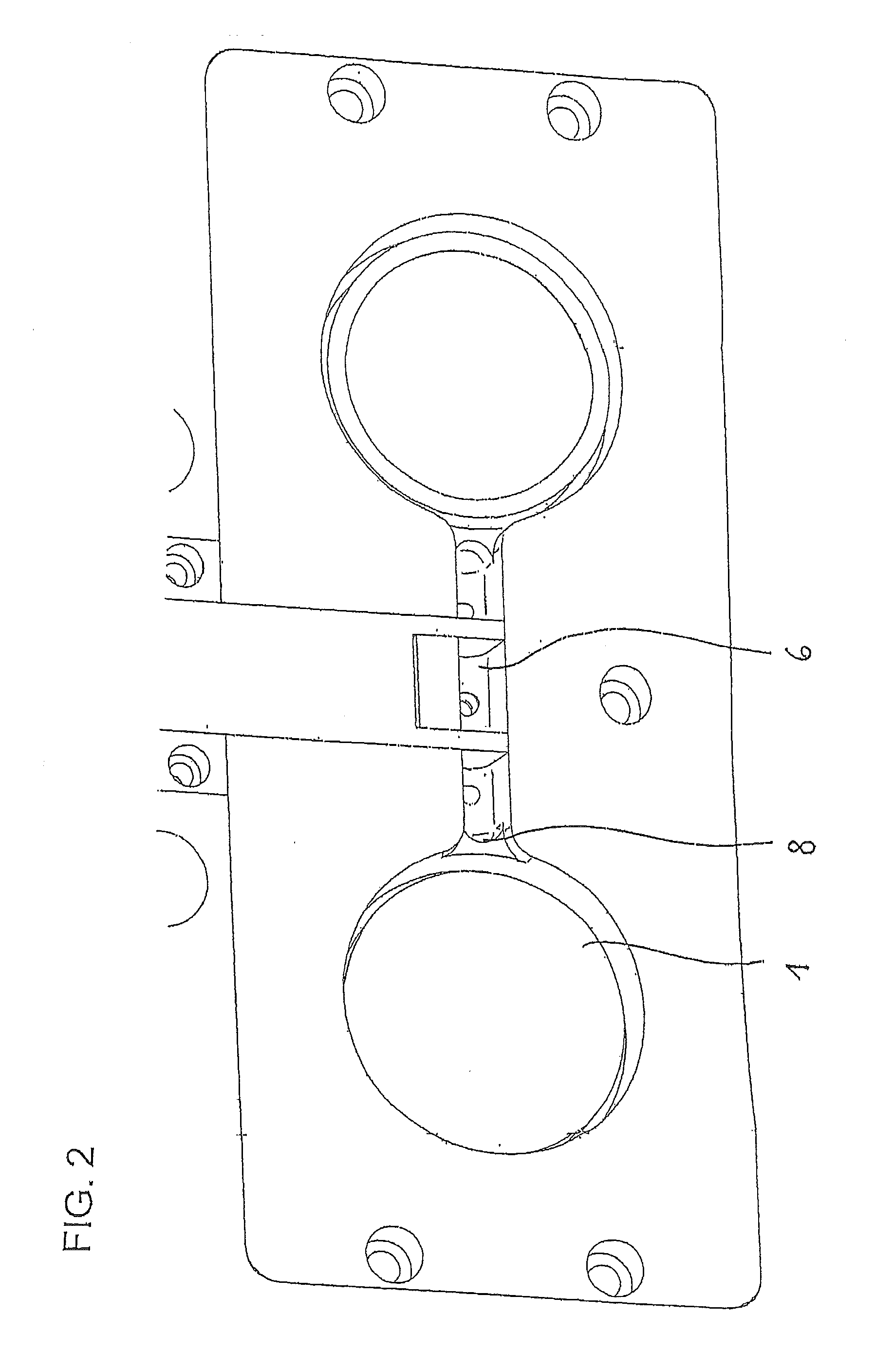
[0008]An embodiment of the present invention is a process for producing a plastic component, comprising injecting plastic melt via a sprue (3, 4, 6, 8) into a cavity (1) of a moulding tool that shapes said plastic component and packing additional plastic melt into said cavity via holding pressure (1) for the purpose of compensating for a volume contraction of the injected plastic melt due to cooling, wherein said plastic melt located in said sprue (3, 4, 6, 8) is kept flowable by means of energy introduced in the region of said sprue for such time until the solidification of any molten plastic in the core of said plastic component.

[0009]Another embodiment of the present invention is the above process, wherein said plastic component is an optical lense or an optical lightguide.

[0010]Another embodiment of the present invention is the above process, wherein said energy is introduced by means of emission of ultrasonic waves directed onto said sprue.

[0011]Another embodiment of the presen...


PUM

PropertyMeasurementUnit
thicknessesaaaaaaaaaa
volumeaaaaaaaaaa
energyaaaaaaaaaa

Abstract

The invention relates to a process for producing plastic components, in particular optical lenses or optical light-guides, wherein plastic melt is injected via a sprue (3, 4, 6, 8) into a cavity (1) of a moulding tool shaping the component and additional plastic melt is after-pressed into the cavity (1) for the purpose of compensating a volume contraction of the injected plastic melt due to cooling. The process is characterised in that the plastic melt located in the sprue (3, 4, 6, 8) is kept flowable by means of energy introduced in the region of the sprue until such time as the molten core of the plastic component has solidified in the course of the after-pressing of plastic melt for the purpose of compensating the volume contraction due to cooling (holding-pressure). The invention further relates to an apparatus for implementing the process.

Description

RELATED APPLICATIONS[0001]This application claims benefit to German Patent Application No, 10 2009 030 782.6, filed Jun. 27, 2009, which is incorporated herein by reference in its entirety for all useful purposes.BACKGROUND OF THE INVENTION[0002]The invention relates to a process for producing plastic components—in particular, optical lenses, optical light-guides and other optical components—wherein plastic melt is injected via a sprue into a cavity of a moulding tool shaping the component and additional plastic melt is pressed into the cavity for the purpose of compensating a volume contraction of the injected plastic melt due to cooling (holding pressure). In this connection the gate may be situated on a narrow side wall of the component. The invention further relates to an apparatus for injection moulding or injection-compression moulding of such plastic components, with a cavity for shaping the plastic component to be produced and with a supply device, for example an injection-m...

Claims


Application Information

Patent Timeline
Patent Type & Authority Applications(United States)
IPC IPC(8): B29D11/00B29C45/00B29C45/72B29C35/08B29C45/76
CPCB29C45/2708B29C45/2737B29K2101/12B29C45/568B29C45/57B29C45/2756
Inventor PROTTE, RAINERKLINKENBERG, CHRISTOPH
Owner BAYER MATERIALSCIENCE AG
Why Eureka
Try Eureka