
Diagnostics Data Collection and Analysis Method and Apparatus

Inactive Publication Date: 2010-12-23
SPX CORP
View PDF99 Cites 43 Cited by
  • Summary
  • Abstract
  • Description
  • Claims
  • Application Information

AI Technical Summary

Problems solved by technology

With such a system, a relatively inexperienced operator may perform advanced diagnostic procedures and diagnose complex operational or medical problems.
However, if an operator or technician is unable to detect an operational problem and the onboard computer has not detected a fault condition, a potential failure condition may in some cases go unnoticed.

Method used


Image

  • Diagnostics Data Collection and Analysis Method and Apparatus
  • Diagnostics Data Collection and Analysis Method and Apparatus
  • Diagnostics Data Collection and Analysis Method and Apparatus

Examples


Embodiment Construction

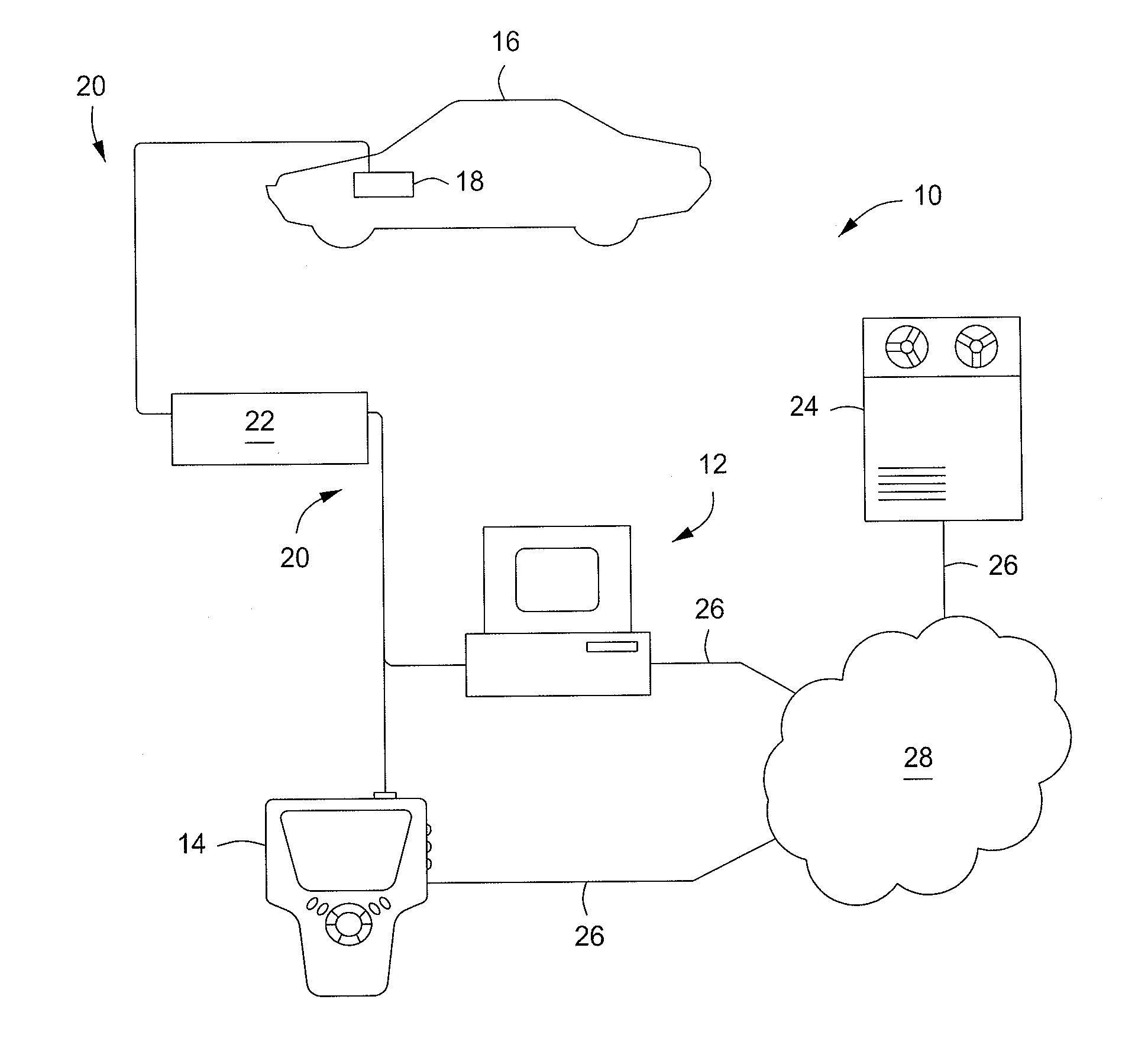
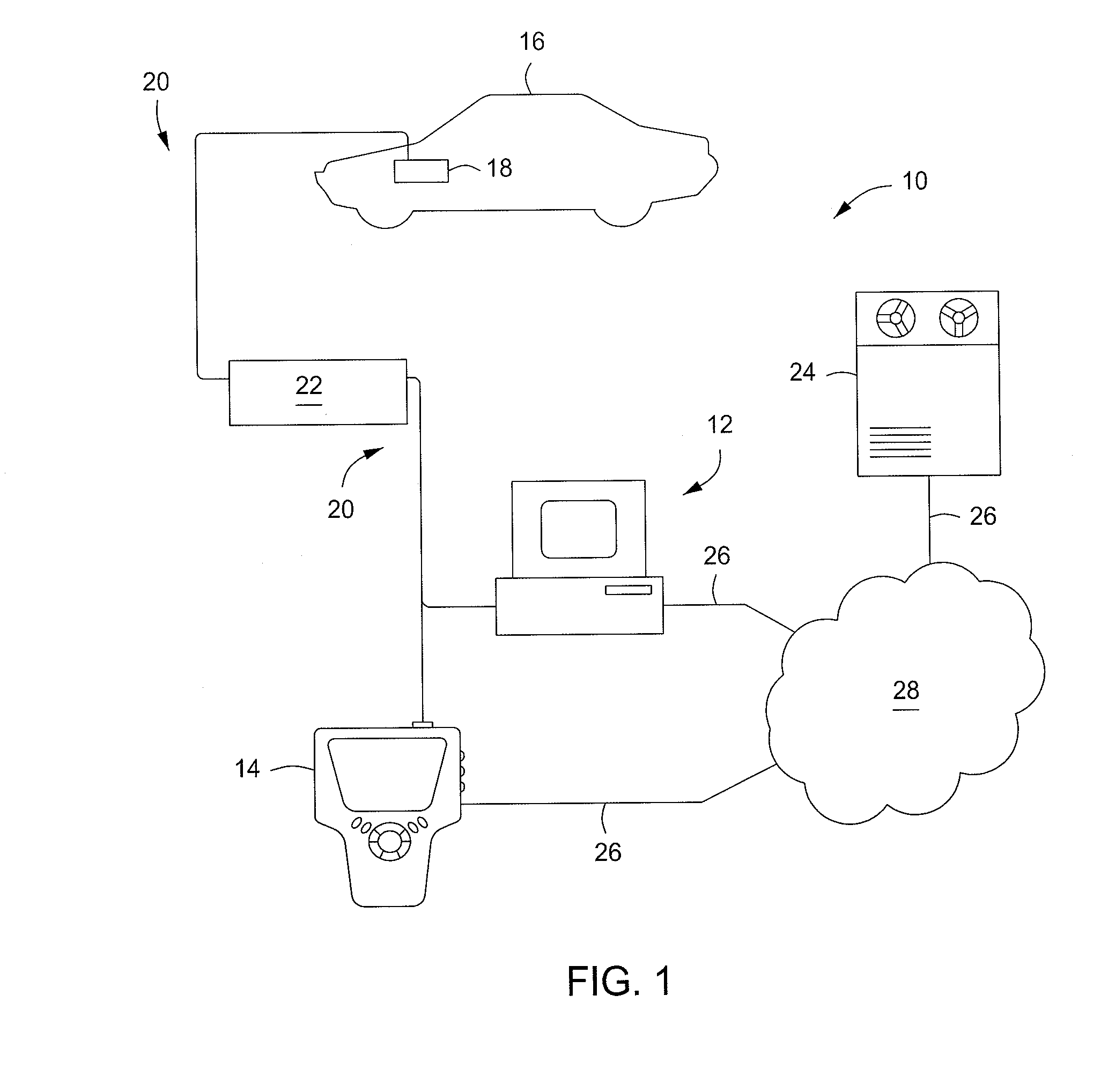
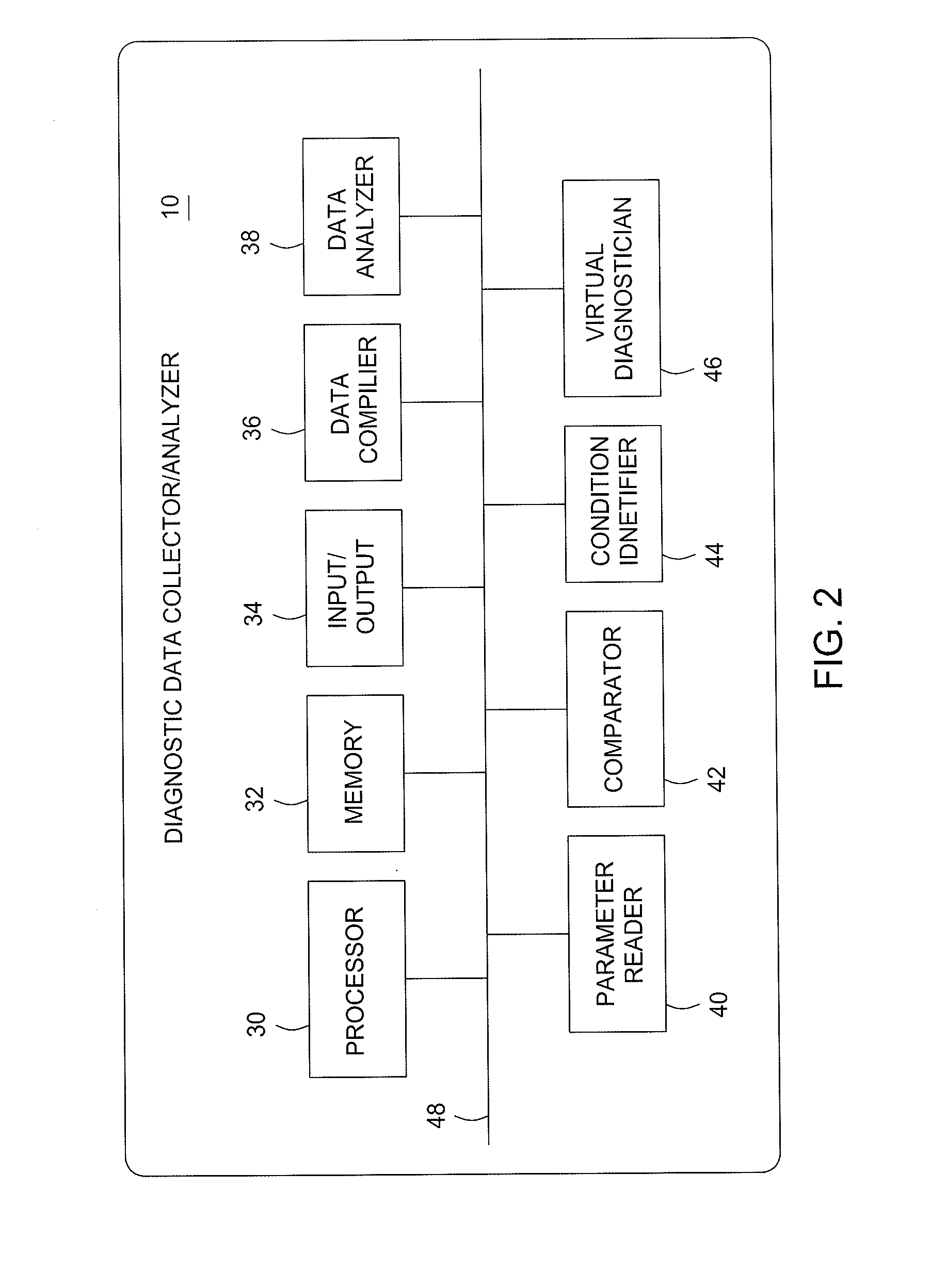
[0031]A representative embodiment in accordance with the present invention provides a vehicle diagnostic data collector / analyzer that can collect historical vehicle operational data corresponding to various normal vehicle operating conditions and vehicle component failure conditions, analyze the data and compare the results of the data analysis to test data gathered from a specific test-subject vehicle in order to diagnose potential failure conditions of vehicle components. The vehicle diagnostic data collector / analyzer can be useful in diagnosing failure conditions that otherwise might be overlooked.

[0032]For example, an operator or technician may in some cases be unable to directly detect a potential failure condition based on a vehicle onboard computer trouble code or codes, or a vehicle operational symptom or symptoms, even though a potential failure condition exists. Nonetheless, in such a case the vehicle diagnostic data collector / analyzer may be able to monitor test-subject v...


PUM


Abstract

A medical diagnostic data collector / analyzer compiles historical vehicle diagnostic data, including measured vital signs from a number of different people from a variety of population types, and performs statistical analyses on various vital sign combinations to establish ranges corresponding to healthy individuals and various disease conditions.

Description

CROSS REFERENCE TO RELATED APPLICATIONS[0001]This application claims benefit of and is a continuation-in-part of U.S. patent application Ser. No. 11 / 478,339, now issued as U.S. Pat. No. 7,751,955, entitled “DIAGNOSTICS DATA COLLECTION AND ANALYSIS METHOD AND APPARATUS TO DIAGNOSE VEHICLE COMPONENT FAILURES,” filed Jun. 30, 2006, which is hereby incorporated by reference in its entirety.FIELD OF THE INVENTION[0002]The present invention relates generally to diagnostic equipment. More particularly, the present invention relates to the collection and analysis of diagnostics data to diagnose operational or functional problems, such as vehicle component failures.BACKGROUND OF THE INVENTION[0003]Diagnostic systems are used by technicians and professionals in virtually all industries to perform basic and advanced system testing functions. For example, in the automotive, trucking, heavy equipment and aircraft industries, diagnostic test systems provide for vehicle onboard computer fault or t...

Claims


Application Information

Patent Timeline
IPC IPC(8): A61B5/00G06Q50/00G06F7/00G06F15/00G16H10/60G16H50/20
CPCG06Q50/22G07C2205/02G07C5/085G07C5/008G16H10/60G16H50/20
Inventor CHINNADURAI, MANOKARGILBERT, HARRY M.LIPSCOMB, EDWARD
Owner SPX CORP
Learn More