Position input device and computer system
a technology of position input and input device, which is applied in the direction of instruments, computing, electric digital data processing, etc., can solve the problems of increasing power consumption of position detector device, and unnecessary transmission of signals from position detector device, so as to reduce power consumption of position pointing device, improve accuracy in detecting position, and reduce battery change and recharge frequency
- Summary
- Abstract
- Description
- Claims
- Application Information
AI Technical Summary
Benefits of technology
Problems solved by technology
Method used
Image
Examples
first embodiment
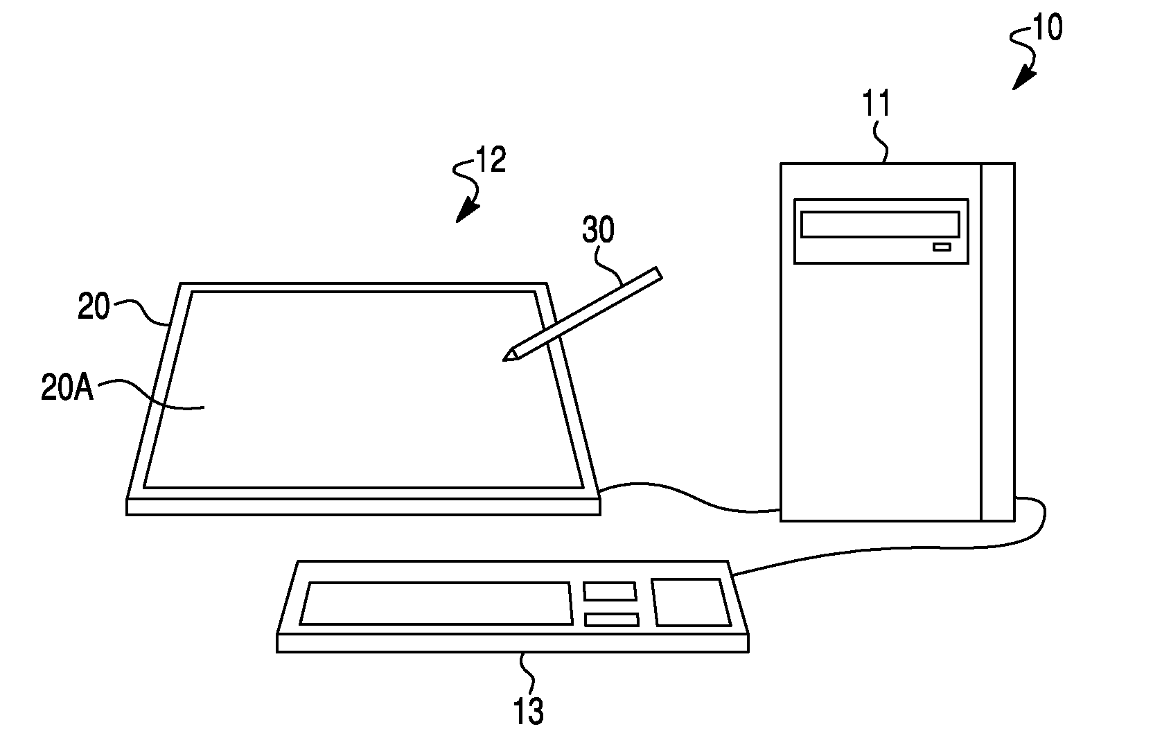
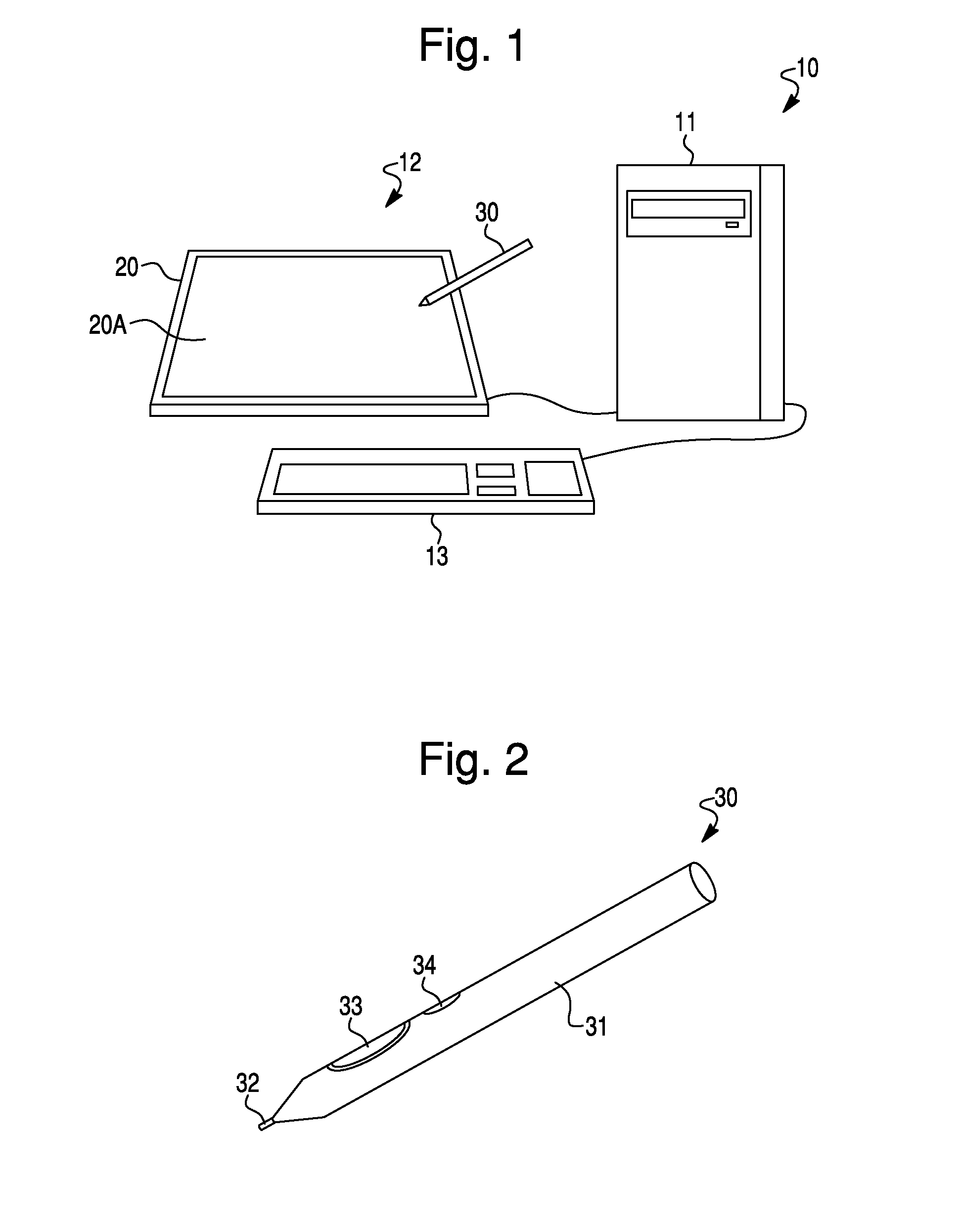
[0087]FIG. 1 shows an overview of a computer system 10 of a first embodiment of the invention.
[0088]In computer system 10 shown in FIG. 1, a monitor 12 and a keyboard 13 are connected to a computer main unit 11. An LCD (Liquid Crystal Display) or other display screen is integrated with a tablet 20 into the monitor 12 to perform position input using a position indicator 30, such as a pen. In addition, a charger 50, as best shown in FIG. 6A as a stand or holder, to charge the position indicator 30, described below, is connected to the computer main unit 11.
[0089]The tablet 20 (position detector device) functions as part of a position input system through use in conjunction with the position indicator 30, and detects a position indicated by the position indicator 30 on an input area 20A of the screen of the monitor 12, and outputs information, e.g., the position coordinates to the computer main unit 11.
[0090]The charger 50 is used to charge the position indicator 30, and is supplied wi...
modified example 1
[0135]FIG. 11 is a flowchart showing charging control processing in a modified example of the above first embodiment. The configuration of this modified example is similar to that of the computer system 10 of the above first embodiment, except for the operation of charging control processing.
[0136]In the charging control processing shown in FIG. 11, the CPU 101 of the computer main unit 11 counts the time elapsed from the previous charging of the position indicator (step S11), and when this elapsed time has reached a prescribed time (step S11: Yes), a charging request message is displayed on the monitor 12 (step S12), and causes the supply of power from the interface portion 107 to the charger 50 to be started (step S13). Then, after a prescribed time has elapsed, the CPU 101 stops the supply of power to the charger 50 (step S14), returns to step S11, and counts the elapsed time.
[0137]In this case, even when the tablet 20 has not received charging request data from the position indi...
modified example 2
[0138]FIG. 12 is a flowchart showing charging control processing in another modified example of the above first embodiment. The configuration of this modified example is similar to that of the system 10 of the above-described first embodiment, except for the operation of charging control processing.
[0139]In the charging control processing shown in FIG. 12, the CPU 101 of the computer main unit 11 counts the time elapsed from the previous charging of the position indicator (step S21). When this elapsed time has reached a prescribed time (step S21: Yes), the CPU 101 determines whether the tablet 20 is able to receive signals transmitted from the position indicator 30 (step S22).
[0140]When no signals transmitted from the position indicator 30 are being received by the tablet 20 (step S22: No), the controller 401 displays a charging request message on the monitor 12 (step S23) and starts the supply of power from the interface portion 107 to the charger 50 (step S24). After a prescribed ...
PUM
 Abstract
Description
Claims
Application Information
 - R&D
- Intellectual Property
- Life Sciences
- Materials
- Tech Scout
- Unparalleled Data Quality
- Higher Quality Content
- 60% Fewer Hallucinations
Browse by: Latest US Patents, China's latest patents, Technical Efficacy Thesaurus, Application Domain, Technology Topic, Popular Technical Reports.
© 2025 PatSnap. All rights reserved.Legal|Privacy policy|Modern Slavery Act Transparency Statement|Sitemap|About US| Contact US: help@patsnap.com


