
Latch assembly

Inactive Publication Date: 2010-12-16
SOLTEAM ELECTRONICS
View PDF11 Cites 8 Cited by
  • Summary
  • Abstract
  • Description
  • Claims
  • Application Information

AI Technical Summary

Benefits of technology

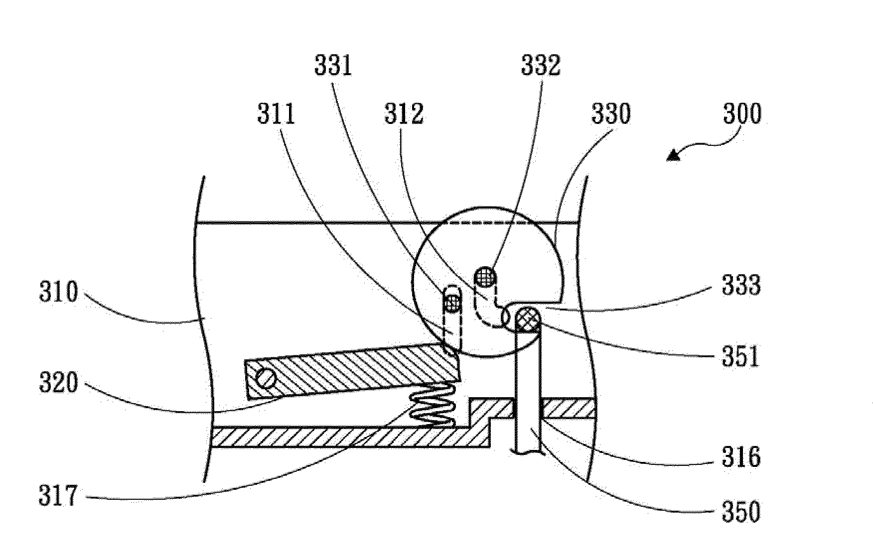
[0008]The main concept of the present invention is to use a driven member capable of both rotation and translation and develop therefrom, through proper mechanism design, a latch assembly that features compact structure, simple components, low costs, high stability, and applicability to doors based on various mechanisms.
[0009]One objective of the present invention is to provide a latch assembly whose components are easy to design and highly applicable. By using a common and popular mechanical design, coupling and decoupling between the components of the latch assembly are reliably achieved so that the latch assembly is enabled to function as a door latch for household appliances, thereby effectively remedying the drawbacks of the conventional devices, such as complicated structure, an excessively large number of components, elevated costs, and high wear and tear.

Problems solved by technology

Despite their advantageously easy and straightforward operation, these two types of latches are nevertheless disadvantaged by their complex structures and numerous components, which require complicated manufacturing processes and high production costs.
Besides, as the aforesaid two types of conventional latches use a considerable number of metal components, their material costs are also high.
Moreover, an electromagnetic valve tends to malfunction as the magnetic property of its components degrades due to long-term use.
A spring-loaded button, on the other hand, is likely to become stuck or loose when its metal parts are rusted, thus having a very limited service life.

Method used


Image

  • Latch assembly
  • Latch assembly
  • Latch assembly

Examples


Embodiment Construction

[0019]The present invention relates to a latch assembly that uses a simple mechanism design based on a driven member capable of rotation and translation so that the latch assembly features a compact structure, simple components, low costs, and high stability.

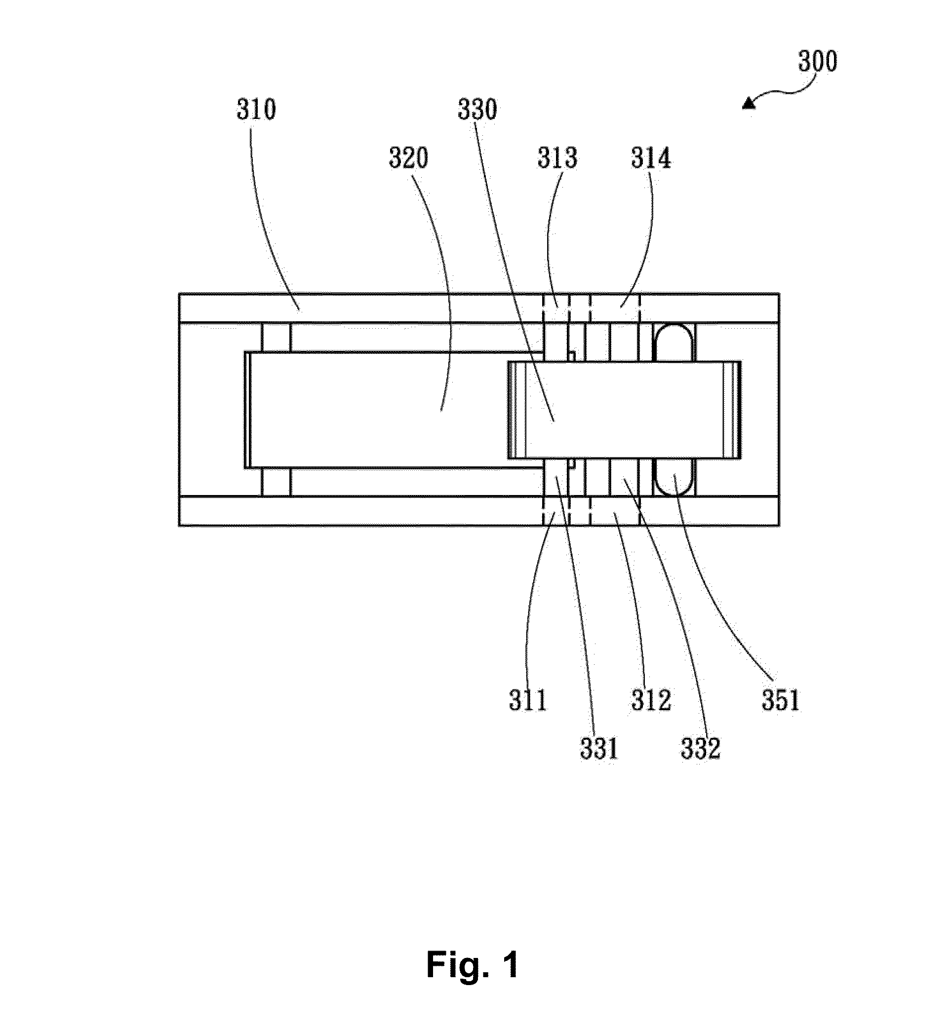
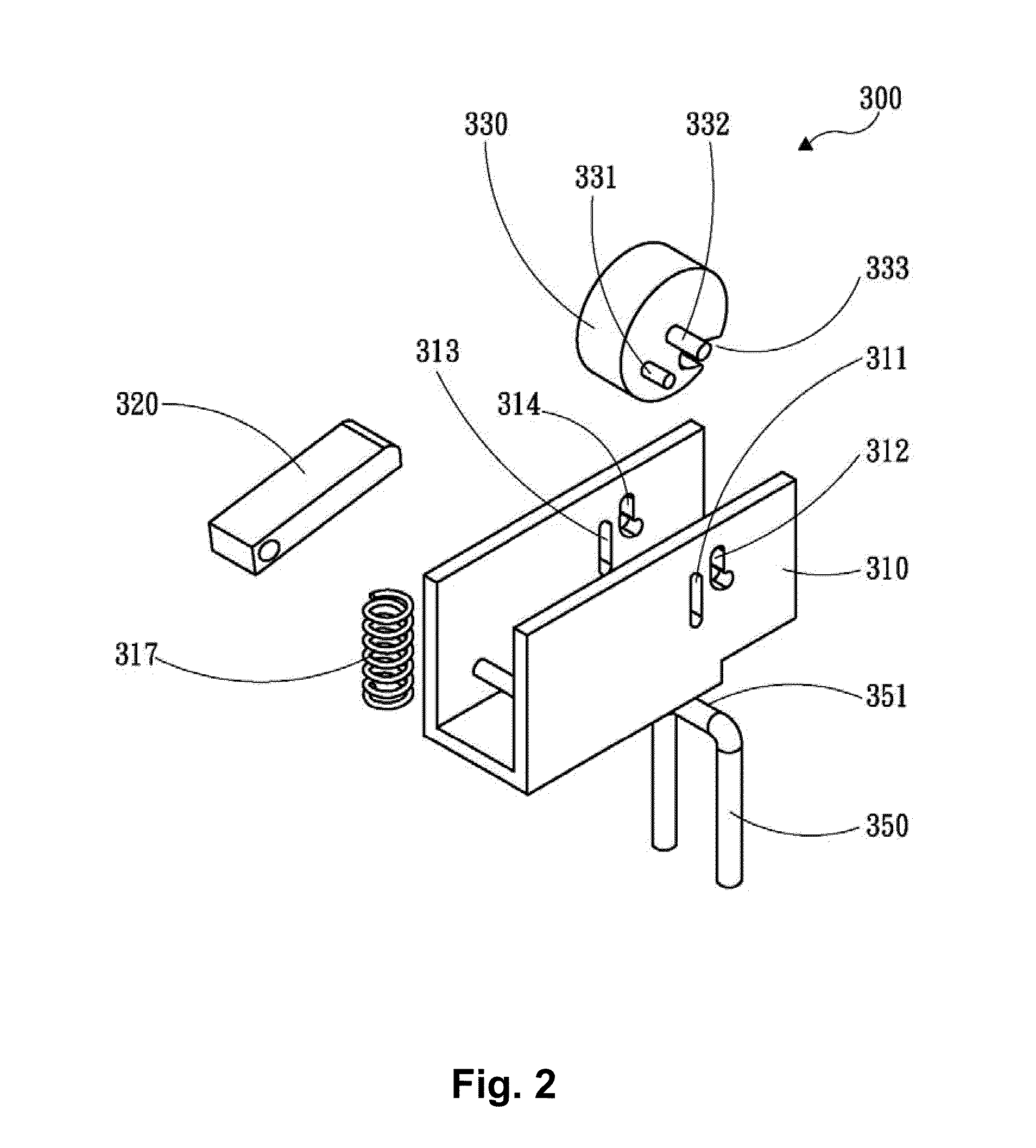
[0020]Please refer to FIGS. 1 and 2 for a top view and an exploded perspective view of a latch assembly 300 according to one preferred embodiment of the present invention. As shown in the drawings, the latch assembly 300 includes an L-shaped body 310, a carrier 320, a driven member 330, a locking tongue 350, and a resilient element 317. Therein, the L-shaped body 310 may be alternatively formed with an acute angle or an obtuse angle, instead of the right angle depicted in the drawings.

[0021]An accommodating space is defined inside the L-shaped body 310. Two pairs of retaining recesses are formed respectively on a first lateral wall and a second lateral wall of the L-shaped body 310 that are opposite to each other. The first reta...


PUM


Abstract

A latch assembly includes a body having an accommodating space, two pairs of retaining recesses, a window, and a resilient element; a carrier received in the accommodating space and having one end pivotally connected to the body and an opposite end abutting against the resilient element; a driven member received in the accommodating space and abutting against the carrier, the driven member including a main shaft, a guide post, and a notched portion corresponding in position to the window of the body; and a driving member having a connecting portion to be inserted into the window and coupled with the notched portion of the driven member so as to form a loose fit with the driven member. When the connecting portion is inserted into the window and coupled with the notched portion, the driven member is drawn by the driving member to move and rotate within the retaining recesses.

Description

BACKGROUND OF THE INVENTION[0001]1. Technical Field[0002]The present invention relates to latches and, more particularly, to a latch assembly that functions mainly on a driven member capable of rotation and translation and is characterized by a compact structure, simple components, and high stability.[0003]2. Description of Related Art[0004]By virtue of the industrial revolution and the advancement of technological civilization, housework which used to take a lot of time and energy to accomplish, such as clothes washing, dish cleaning, baking, and cooking, has now been taken care of or assisted by various household appliances like washing machines, clothes dryers, dish washers, ovens, and microwave ovens so that the chores are easily and efficiently done. In a sense, these household appliances have become necessaries to the modern life.[0005]Although these household appliances operate upon different principles and provide different functions, they are actually similar in structure a...

Claims


Application Information

Patent Timeline
IPC IPC(8): E05C19/10
CPCE05C5/00E05C19/024Y10T292/0946
Inventor WANG, YA-HSIUNGPHANG, CHI-MENG
Owner SOLTEAM ELECTRONICS
Learn More