Eureka AIR delivers breakthrough ideas for toughest innovation challenges, trusted by R&D personnel around the world.

Apparatus and Method for Deterministic Control of Surface Figure During Full Aperture Polishing

a technology of surface figure and deterministic control, applied in the direction of abrasive surface conditioning devices, lapping machines, instruments, etc., can solve the problems of optical elements that are not useful for their intended purposes, optical elements that are damaged,

Active Publication Date: 2010-12-09
LAWRENCE LIVERMORE NAT SECURITY LLC
View PDF11 Cites 11 Cited by
  • Summary
  • Abstract
  • Description
  • Claims
  • Application Information

AI Technical Summary

Benefits of technology

[0017]According to another embodiment of the present invention, a polishing system includes a lap configured to contact a workpiece for polishing the workpiece, and a septum configured to contact the lap. The septum has an aperture formed therein to receive the workpiece, and the lap is configured to contact the workpiece through the aperture. The polishing system further includes a first device configured to couple to the workpiece and place a first amount of pressure between the workpiece and the lap, and a second device coupled to the septum and configured to place a second amount of pressure between the septum and the lap to compress the lap as the workpiece is polished by the lap, wherein the second amount of pressure is three or more times the first amount of pressure.
[0018]According to a specific embodiment of the polishing system, the compression of the lap is configured to inhibit the workpiece from compressing the lap as the workpiece is polished by the lap. The compression of the lap is configured to substantially planarize the lap as the workpiece is polished by the lap. The polishing system may further include the workpiece.
[0019]According to another embodiment of the present invention, a polishing method is provided for pressing a lap with a septum to compress the lap during polishing of a workpiece to inhibit the workpiece from compressing the lap during the polishing. The method includes pressing on a workpiece with a first forcing device to place a first amount of pressure between a lap and a workpiece; and pressing on a septum with a second forcing device to place a second amount of pressure between the septum and the lap, wherein the septum has an aperture formed therein and the workpiece is configured to contact the lap through the aperture, and wherein the second amount of pressure is three or more times greater than the first amount of pressure. According to a specific embodiment, the method further includes rotating the lap with respect to the septum and the workpiece.

Problems solved by technology

Without the optician's monitoring and talents, the surfaces of optical elements during grinding and polishing are highly likely to have a shape that is not desired.
That is, the resultant optical elements might not be useful for their intended purposes, such as shaping radiation fronts as desired, or the optical elements might be damaged (e.g., in high energy applications) during use due to less than optimal surface shape.

Method used


Image

  • Apparatus and Method for Deterministic Control of Surface Figure During Full Aperture Polishing
  • Apparatus and Method for Deterministic Control of Surface Figure During Full Aperture Polishing
  • Apparatus and Method for Deterministic Control of Surface Figure During Full Aperture Polishing

Examples


Embodiment Construction

[0039]This invention provides an apparatus and a method for shaping an optical surface. More particularly, the invention provides an apparatus and a method for generating a deterministic polishing process for an optical surface.

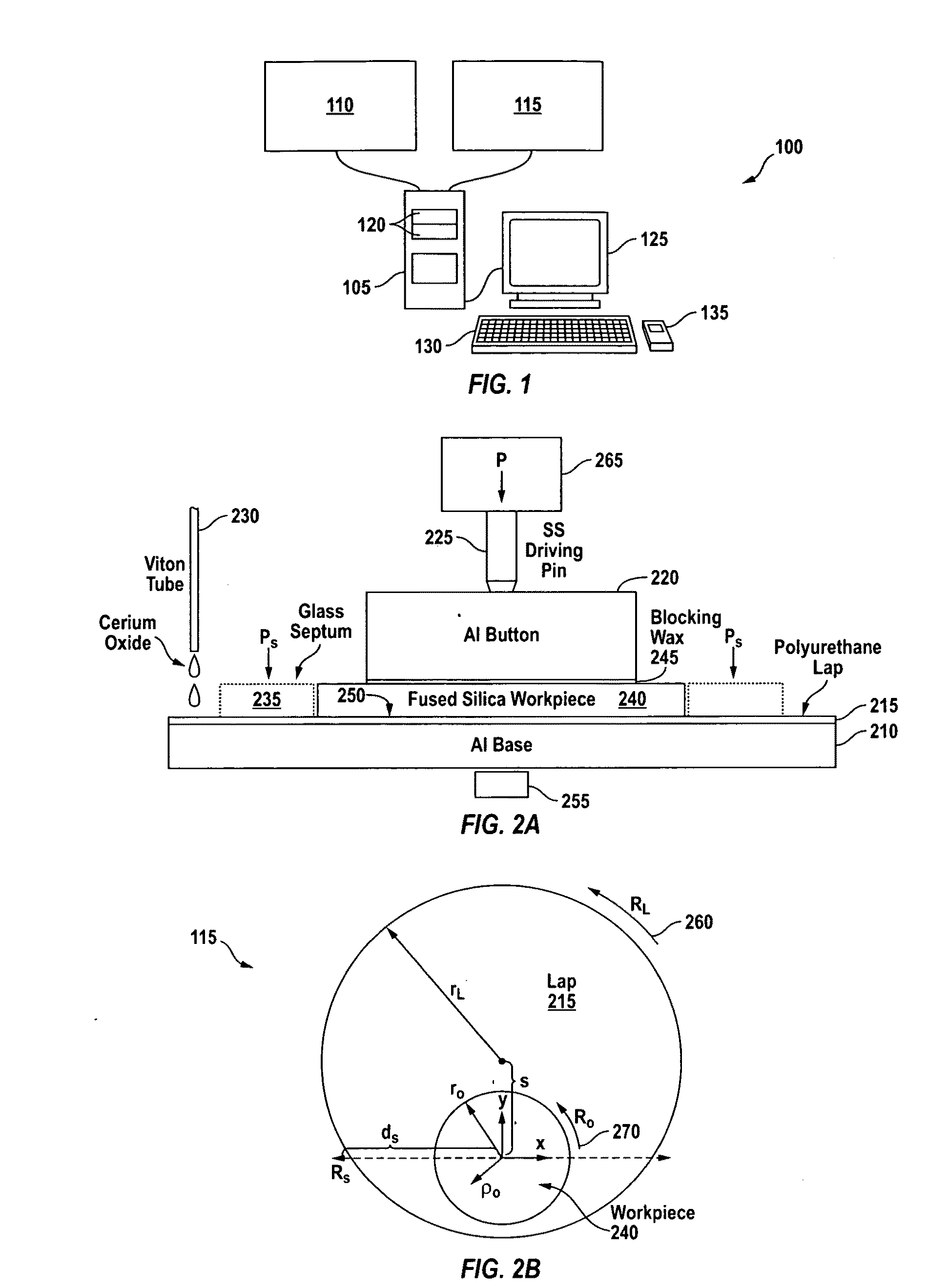
[0040]FIG. 1 is a simplified block diagram of a polishing system 100 according to one embodiment of the present invention. Polishing system 100 includes a computer system 105, a set of controls 110, and a set of polishing devices 115. According to an alternative embodiment, polishing system 100 includes the set of controls 110 and the set of polishing devices 115, but does not include computer system 105. Polishing system 100 is configured to polish a workpiece, such as an optical element (sometimes referred to in the art as an optic), as described below. Polishing system 100 is sometimes referred to in the art as a polisher.

[0041]Computer system 105 may be a personal computer, a work station, a laptop computer, a set of computers, a dedicated computer, or th...


PUM

PropertyMeasurementUnit
friction forceaaaaaaaaaa
pressure distributionaaaaaaaaaa
time periodsaaaaaaaaaa

Abstract

A polishing system configured to polish a lap includes a lap configured to contact a workpiece for polishing the workpiece; and a septum configured to contact the lap. The septum has an aperture formed therein. The radius of the aperture and radius the workpiece are substantially the same. The aperture and the workpiece have centers disposed at substantially the same radial distance from a center of the lap. The aperture is disposed along a first radial direction from the center of the lap, and the workpiece is disposed along a second radial direction from the center of the lap. The first and second radial directions may be opposite directions.

Description

CROSS REFERENCE TO RELATED APPLICATIONS[0001]This application claims priority to U.S. Provisional Patent Application No. 61 / 148,236, filed Jan. 29, 2009, titled “DETERMINISTIC CONTROL OF SURFACE FIGURE DURING FULL APERTURE POLISHING,” of Tayyab I. Suratwala et al., which is incorporated by reference herein in its entirety for all purposes.STATEMENT AS TO RIGHTS TO INVENTIONS MADE UNDER FEDERALLY SPONSORED RESEARCH OR DEVELOPMENT[0002]The United States Government has rights in this invention pursuant to Contract No. DE-AC52-07NA27344 between the United States Department of Energy and Lawrence Livermore National Security, LLC.BACKGROUND OF THE INVENTION[0003]This invention relates to an apparatus and a method for shaping an optical surface. More particularly, the invention relates to an apparatus and a method for generating a deterministic polishing process for an optical surface.[0004]Optical elements, such as lenses and mirrors, in an optical system provide for the shaping of radiat...

Claims


Application Information

Patent Timeline
Patent Type & Authority Applications(United States)
IPC IPC(8): B24B49/00B24B7/00B24B1/00B24B37/04
CPCB24B1/00B24B7/228B24B37/04B24B37/10B24B13/00B24B37/042B24B53/017B24B37/105B24B37/32B24B53/12
Inventor SURATWALA, TAYYAB ISHAQFEIT, MICHAEL DENNISSTEELE, WILLIAM AUGUSTUS
Owner LAWRENCE LIVERMORE NAT SECURITY LLC
Why Eureka
Eureka Blog
Learn More