
Shade analysis device

a technology of a device and a light source, applied in the field of light source analysis, can solve the problems of affecting the brightness of the sun at two locations that are only a few feet apart, and the sun may be blocked for the entire month or more, and achieve the effect of maximizing the amount of direct sunligh

Inactive Publication Date: 2010-12-02
SOLMETRIC
View PDF3 Cites 26 Cited by
  • Summary
  • Abstract
  • Description
  • Claims
  • Application Information

AI Technical Summary

Benefits of technology

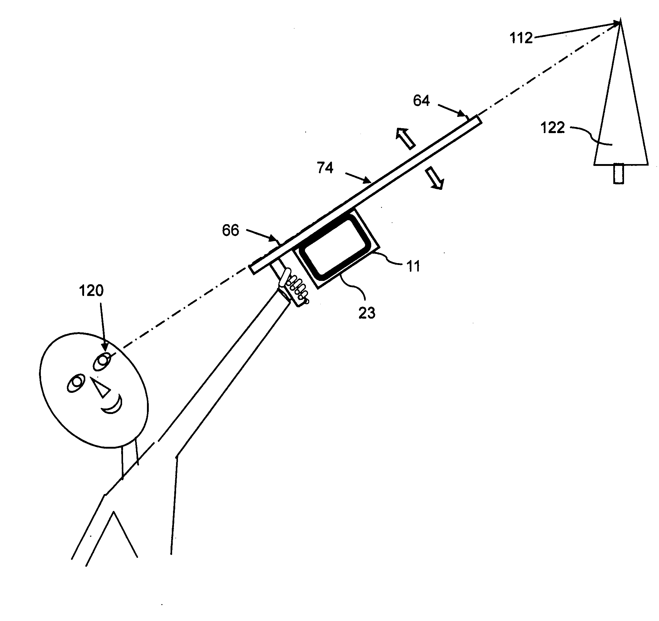
"The present invention is an integrated, portable shade analysis device that allows users to trace the skyline at a given location and analyze the light and solar energy that is received at that location. The device computes statistics on the light and solar energy, including hours of sunlight, shade factor, available solar energy, optimum position for solar panels, and revenue generated from a solar installation. The device can also simulate the removal of a solar obstruction and display the results in real-time. The device includes a GPS receiver, accelerometer, electronic compass, and digital camera, and a program that runs on a portable electronic device. The program allows users to trace the skyline by using the device's measurement edge or cross-hairs, or by panning the horizon and capturing images of the skyline. The captured images can be stitched together to create a seamless view of the skyline."

Problems solved by technology

The effect of a solar obstruction, such as a tree, may result in a significant difference in sunlight at two locations that are only a few feet apart.
For example, at one location sunlight may be obstructed only over a very limited time interval, while at another location, just a few meters away, sunlight may be obstructed for the entire month or more.

Method used


Image

  • Shade analysis device
  • Shade analysis device
  • Shade analysis device

Examples


Embodiment Construction

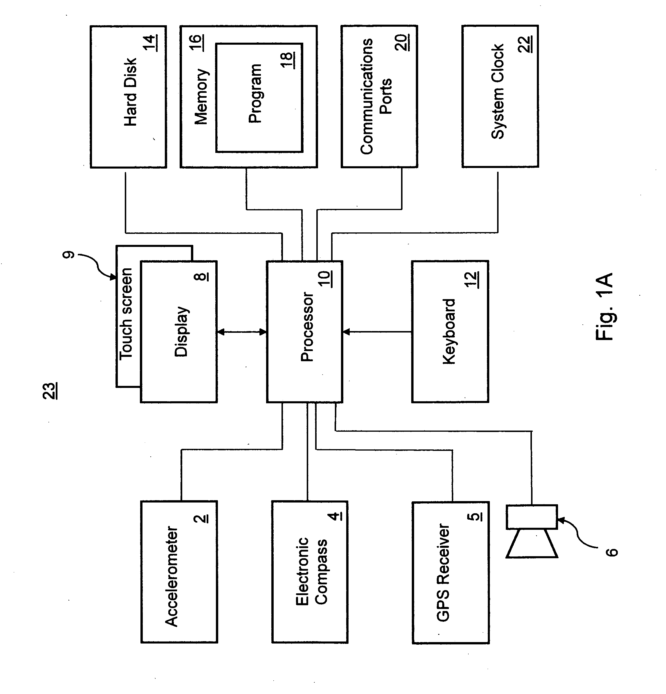
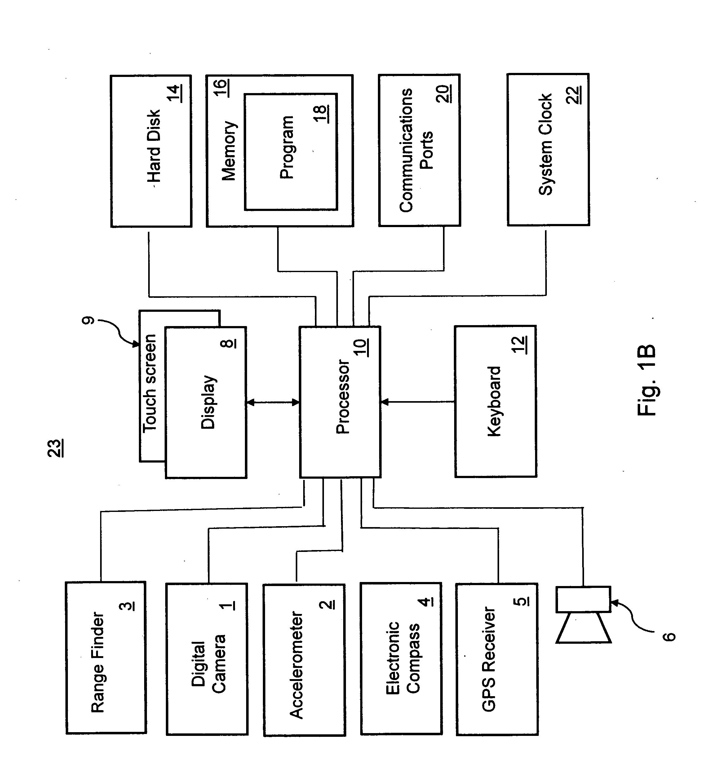
[0037]FIGS. 1A, 1B show schematics of typical components of a shade analysis device 23 according to embodiments of the present invention. The shade analysis device 23 includes an accelerometer 2 or other device suitable to measure the elevation, or tilt angle, of the shade analysis device 23 in the orthogonal reference directions X, Y, Z (shown in FIG. 3). The accelerometer 2 typically has an accuracy of one degree and typically provides samples representing the elevation, or tilt angle, at a sample update rate of 100 times per second. A processor 10 performs data collection and manipulation, and has an associated memory 16 that is sufficient to store a program 18 while being executed, and to store results. The memory 16 may include a hard disk 14, flash memory or other solid-state memory, and / or other form of non-volatile memory for storing the program 18 and user settings, or for archiving acquired samples or results for future use. The shade analysis device 23 has an associated d...


PUM


Abstract

A shade analysis device includes an accelerometer providing samples that represent an elevation defined by a sighting reference, an electronic compass providing samples that represent an azimuth heading defined by the sighting reference, and a processor under the control of a program included in the shade analysis device, acquiring an array of the samples that represent an azimuth heading and an array of corresponding samples that represent the elevation, in response to tracing with the sighting reference, a skyline at an interface between an open sky and at least one solar obstruction over a range of azimuth headings.

Description

CROSS-REFERENCE TO RELATED APPLICATIONS[0001]Pursuant to 35 U.S.C. section 119(e)(1), this application for patent claims priority to the filing dates of U.S. Provisional Patent Application Ser. No. 61 / 183,495 filed 2 Jun. 2009, U.S. Provisional Patent Application Ser. No. 61 / 187,045 filed 15 Jun. 2009, and U.S. Provisional Patent Application Ser. No. 61 / 254,645 filed 23 Oct. 2009, all of which are herein incorporated by reference.BACKGROUND OF THE INVENTION[0002]The present invention is in the technical field of shade analysis. More particularly, the present invention is in the technical field of tools for the analysis of the sunlight and solar energy that can be captured at a particular geographic location.[0003]Shade analysis includes determining the impact of trees, buildings or other solar obstructions on the amount of sunlight that falls on a given geographic location. Shade analysis typically involves acquiring the profile of the skyline, which is the interface between the ope...

Claims


Application Information

Patent Timeline
Patent Type & Authority Applications(United States)
IPC IPC(8): H04N7/18H04M1/00G06F19/00
CPCG01C15/00G01W1/12
Inventor MACKENZIE, SIMON ANDREW
Owner SOLMETRIC
Learn More