Rotating Electric Machine and Manufacturing Method Thereof
- Summary
- Abstract
- Description
- Claims
- Application Information
AI Technical Summary
Benefits of technology
Problems solved by technology
Method used
Image
Examples
embodiment 1
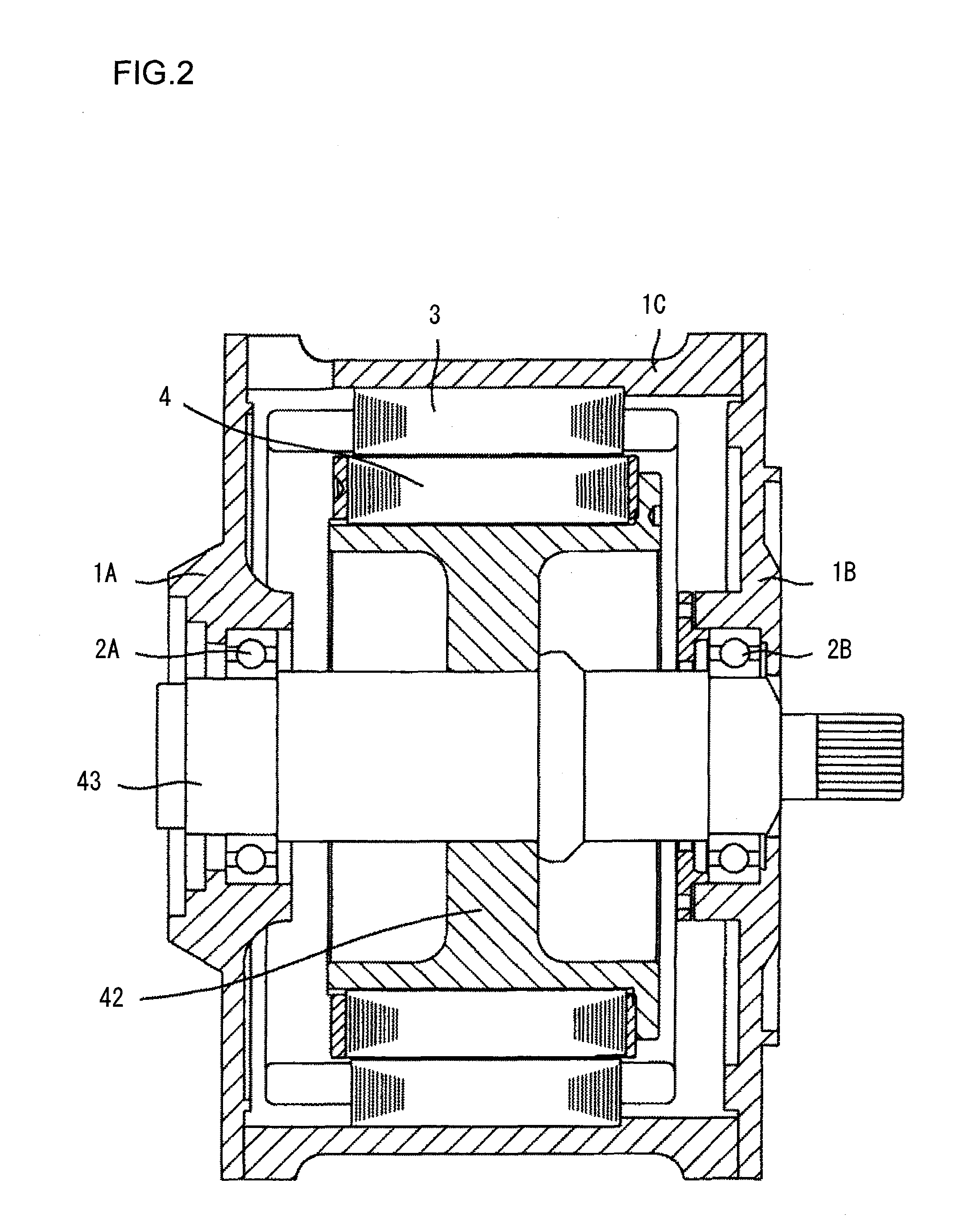
[0056]FIG. 2 is an overall cross-section view of the rotating electric machine. A stator 3 is fixed to a housing 1c with fixing the stator core to the housing 1c by interference fitting, and a rotor 4 includes a spider 42 and a shaft 43, being rotatably supported by bearings 2a and 2b. Here, the rotor 4 is supported to be rotatable against the stator 3 with small gap between the rotor and the stator.
[0057]The manufacturing method of rotor core will be explained. FIG. 3 shows how each plate of the rotor core is punched from magnetic steel plate. The magnetic steel plate, a material, is manufactured by rolling, has a deviation in plate thickness at a right angle to the rolling direction of the steel plate shown in FIG. 3, and is thinner towards one side 411a than the other side 411b. Each rotor plate of a rotor core having two key shapes 412 with the same shape in the inner circumference, and these two key shapes 412 are arranged at 90 degrees to the rolling direction of the magnetic ...
embodiment 2
[0063]Next, an example of the application in the embodiment 1, in which the rotor core 41 is constructed by dividing the laminated plates into blocks each with a thickness divided from the total lamination thickness and rotary stacking of each block is adopted, will be explained. All the processes except the lamination structure of the rotor core are the same as those of the embodiment 1.
[0064]FIG. 8 illustrates the structure of the rotor core 41 in which rotary stacking of blocks is applied. Each plate in a laminated block with a predetermined thickness is punched in the same manner as that in the embodiment 1, and each block is rotated by 180 degrees when the rotation is necessary for balancing, thus the rotor core being constructed with the stacked blocks. It should be understood that when such rotary stacking is applied for stacking the blocks, an identification marking, is provided in the position of each block where the mass of each block is minimum, namely in the vicinity of ...
embodiment 3
[0067]The rotor of an induction motor to which the present embodiment is applied will be explained.
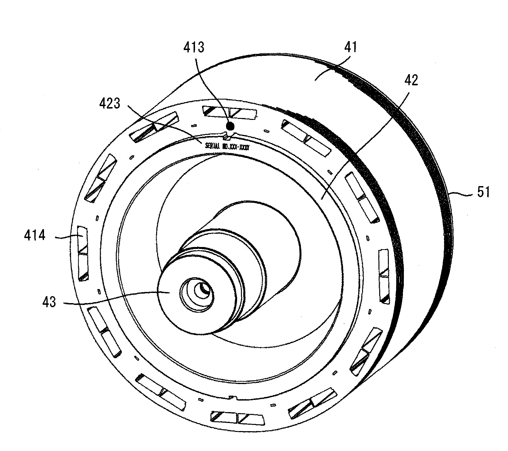
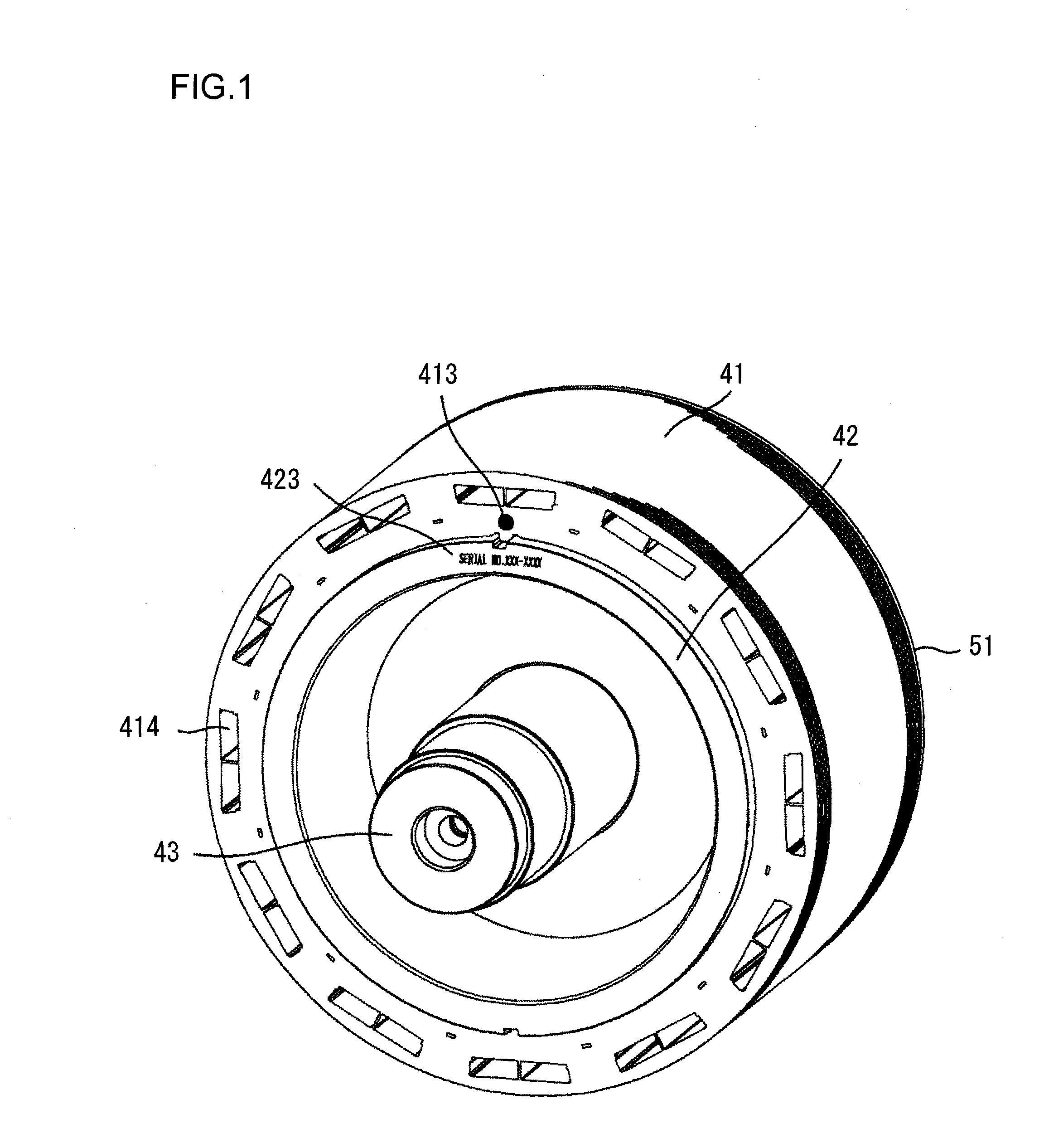
[0068]FIG. 9 shows a perspective view of the rotor core 41 of the induction motor. In the case of the induction motor, in the same manner as the embodiment 1, a steel plate is punched so that the key shapes 412 are arranged at 90 degrees to the rolling direction of the magnetic steel plate, and laminated to a predetermined lamination thickness without applying rotary lamination. Then, a lamination thickness measurement is performed, and the identification marking 413 is provided on the key shape 412a position, in which lamination thickness is smaller.
[0069]Next, a temporary shaft is inserted and aluminium or copper is die-casted so as to form a conductor section 44 of a squirrel-cage rotor as shown in FIG. 10.
[0070]FIG. 11 shows a perspective view of the rotor into which the shaft 43 is inserted. The shaft 43, which is inserted thereinto, is provided with keyways which correspond to th...
PUM
| Property | Measurement | Unit |
|---|---|---|
| Angle | aaaaa | aaaaa |
| Weight | aaaaa | aaaaa |
| Thickness | aaaaa | aaaaa |
Abstract
Description
Claims
Application Information
 - R&D
- Intellectual Property
- Life Sciences
- Materials
- Tech Scout
- Unparalleled Data Quality
- Higher Quality Content
- 60% Fewer Hallucinations
Browse by: Latest US Patents, China's latest patents, Technical Efficacy Thesaurus, Application Domain, Technology Topic, Popular Technical Reports.
© 2025 PatSnap. All rights reserved.Legal|Privacy policy|Modern Slavery Act Transparency Statement|Sitemap|About US| Contact US: help@patsnap.com


