
Wind turbine accelerator panels and method of making same

a technology of accelerator panels and wind turbines, applied in the direction of wind energy generation, wind motors with parallel air flow, liquid fuel engine components, etc., can solve the problems of requiring a coating to withstand the elements, is relatively heavy and expensive, and other materials have also been employed but have not been wholly successful, so as to reduce the thickness of overlapping relationships and severe curvature

Inactive Publication Date: 2010-11-25
STATE OF CONNECTICUT DEPT OF ECONOMIC & COMMUNITY DEV
View PDF0 Cites 14 Cited by
  • Summary
  • Abstract
  • Description
  • Claims
  • Application Information

AI Technical Summary

Benefits of technology

The present invention provides a tower for supporting wind turbines at elevated positions for enhanced wind velocities. An accelerator is mounted on the tower and has a gradually arcuate front surface to divide wind impinging thereon into a pair of discrete diverging streams of air flowing around opposite sides of the accelerator. The accelerator supports a multiplicity of similar large monolithic panels of lightweight thermoformed construction arranged in vertically stacked horizontal rows, each panel being flexed toward a lesser degree of curvature when mounted and with narrow elongated edge portions in overlapping relationship with all four adjacent panels to accommodate relative sliding action during panel expansion and contraction. The panels are manufactured with a multiplicity of small strength enhancing projections on their interior surfaces and with an open-ended vertical notch for receiving a vertical structural supporting member in tight engagement therewith to prevent accidental or unintended relative rotation of the panel. The method of manufacturing the panels is believed to produce the highest possible ratio of strength to weight in plastic panel construction.

Problems solved by technology

Sheet steel has been used in the past for the external covering on accelerators but requires a coating to withstand the elements and is relatively heavy and expensive.
Other materials have also been employed but have not been wholly successful.

Method used


Image

  • Wind turbine accelerator panels and method of making same
  • Wind turbine accelerator panels and method of making same
  • Wind turbine accelerator panels and method of making same

Examples


Embodiment Construction

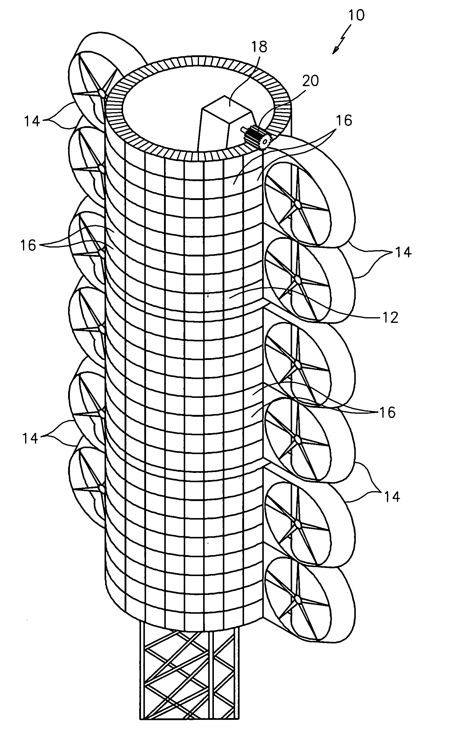
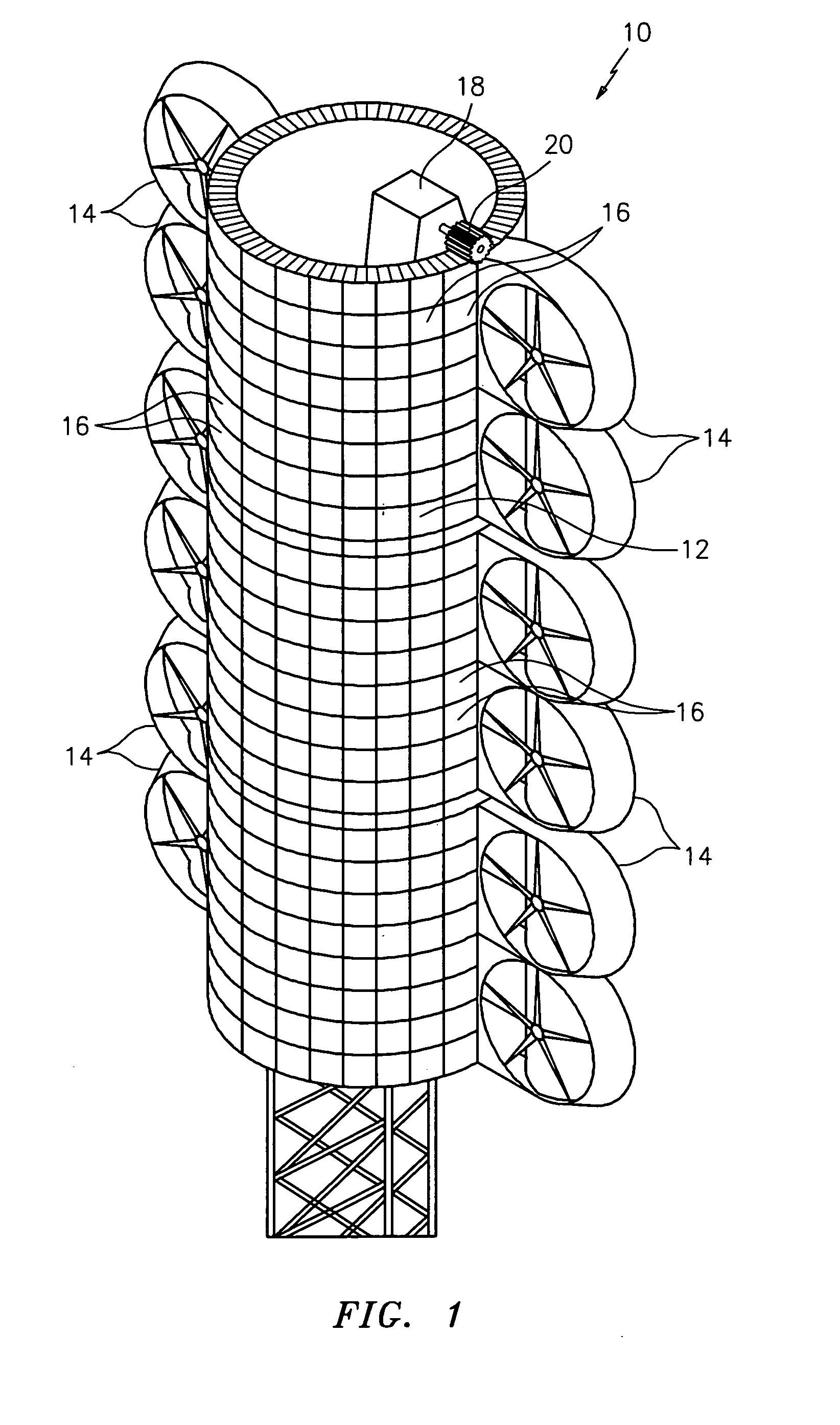
[0028]Referring particularly to FIG. 1 a wind turbine tower is indicated generally at 10 and has a vertically elongated cylindrical accelerator 12 mounted thereon. The accelerator 12 supports six 6 pairs of wind turbines 14,14 but as stated, it will be apparent that the present invention is applicable to a wide variety of accelerator and turbine systems. The external covering for the accelerator 12 is provided by horizontal rows of panels 16,16 of the present invention stacked vertically with sixteen (16) panels in each row and twenty-four (24) horizontal rows of panels. In the aggregate, the panels 16,16 provide a smooth continuous external front surface throughout for the accelerator 12 which separates wind engaging the same into two discrete horizontally diverging and accelerating streams of air respectively directed to the turbines 14,14 on opposite sides of the accelerator. A small motor 18 and an associated spur and annular rack gear system 20 is controlled by a wind direction...


PUM

PropertyMeasurementUnit
thicknessaaaaaaaaaa
thicknessaaaaaaaaaa
thicknessaaaaaaaaaa

Abstract

A vertically sectioned cylindrical accelerator for mounting pairs of wind turbines respectively on opposite sides thereof has a covering of twin-sheet thermoformed plastic panels which are smooth on the outside but carry a multiplicity of small cone-shaped projections on their interior surface. The panels are mounted on a structural member by a single central bolt for free expansion and contraction with variation in ambient temperature. The panels are manufactured in a twin-sheet thermoforming operation wherein one sheet is maintained with a smooth surface and the second sheet is provided with the cone-shaped projections, the two sheets being fused together to form an integral panel of lightweight and high strength characteristics.

Description

BACKGROUND OF THE INVENTION[0001]Wind turbine electrical generating systems have employed various accelerators for initially engaging the wind and directing the same in two diverging streams of air to a pair of wind turbines mounted on opposite sides of the accelerators. As will be apparent, a covering for an accelerator should be lightweight and of high structural integrity with a smooth continuous external surface for efficient interaction with the wind. Sheet steel has been used in the past for the external covering on accelerators but requires a coating to withstand the elements and is relatively heavy and expensive. Other materials have also been employed but have not been wholly successful.[0002]It is the general object of the present invention to provide large monolithic thermoformed twin-sheet plastic panels which are light in weight but which exhibit a high degree of structural integrity and are ideally suited for use as external wind engaging covering on accelerators.[0003...

Claims


Application Information

Patent Timeline
Patent Type & Authority Applications(United States)
IPC IPC(8): E04C2/30E04C2/34F03D1/02B32B37/02F03D9/00
CPCE04C2/20E04C2/34F03D1/02F03D1/04Y02E10/728F05B2240/13F05B2240/131F05B2240/40Y02E10/725F03D11/04F03D13/20Y02E10/72Y02P70/50F03D13/10
Inventor FALCONE, ANDREW J.LEACH, DAVID HINMANSTREETER, JAMES N.
Owner STATE OF CONNECTICUT DEPT OF ECONOMIC & COMMUNITY DEV
Learn More